CAN Firmware Connection Notes
Wiring Instructions
Please complete the following three steps in order:
Step 1: Set the DIP Switches
- Power Off First: Unplug all power sources.
- Locate DIP Switches: Turn the tool board over. Find the DIP switch group on the back.
- Set to Position: To use CAN mode, set all switches to the position shown in the example below.
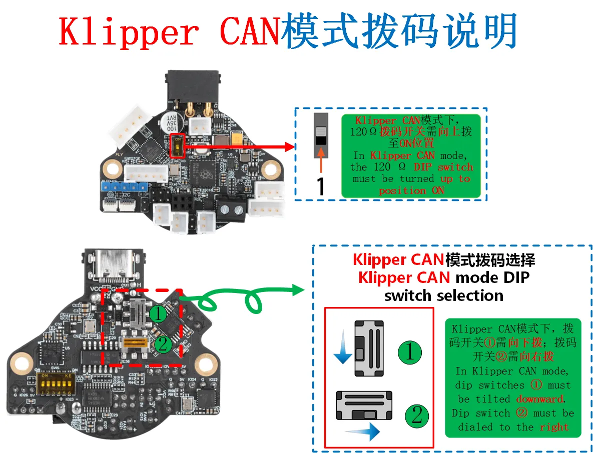
Important: After changing the DIP switches, you must re-flash the corresponding firmware (this guide uses CAN firmware).
Step 2: Connect the Wires
- Keep Power Off: Do not apply power during the entire wiring process.
- Prepare Cable: Use the
XT30(2+2)-F4-core data cable. Its color definitions are as follows:- Red (VCC): Connect to 12V-24V power positive
- Black (GND): Connect to power negative
- Yellow (CAN-H): Connect to the H terminal of the CAN expansion port
- White/Green (CAN-L): Connect to the L terminal of the CAN expansion port
- Connect Devices:
- Plug the
XT30(2+2)-Fconnector of the cable into the tool board. - Connect the cable's terminal block to a UTOC module or a mainboard flashed with the "USB Bridge CAN" firmware.
- Finally, connect the UTOC module or mainboard to your host computer (e.g., FLY Pi or Raspberry Pi) via a USB cable.
- Plug the
Step 3: Configure and Check the Termination Resistor
To ensure signal stability, the termination resistor must be correctly connected. Please configure according to the table below and measure while powered off:
| Device | Instructions |
|---|---|
| Tool Board | Find and plug in the jumper cap labeled 120Ω. |
| Mainboard | If connecting to a mainboard, also plug in its 120Ω jumper cap. |
| UTOC Module | Has built-in resistor*. |
How to Check:
- Ensure the system is completely powered off.
- Use a multimeter to measure the resistance between CAN-H and CAN-L on the tool board's CAN port.
- Result Judgment:
- Approx. 60Ω: Normal. Termination resistors at both ends are correctly connected.
- Approx. 140Ω: Possibly CAN-H and CAN-L are swapped.
- Approx. 120Ω: No
120Ωresistor installed or a wire is broken. - Approx. 90Ω: Only one
120Ωresistor is installed. - Approx. 40Ω: Possibly an extra resistor exists. Check intermediate nodes.
Summary in one sentence: Power off first, set DIP switches correctly, plug in wires correctly, connect the 120Ω jumper caps at both ends, and finally measure if the resistance is around 60Ω.
Checklist:
- Operated with power off throughout
- All DIP switches are set to down (CAN mode)
- Tool board
120Ωjumper cap is installed - Mainboard (if applicable)
120Ωjumper cap is installed - CAN data cable is securely connected
- Measured resistance is approx. 60Ω
CAN Network Configuration and Troubleshooting
Step 1: Check if the Host Computer Recognizes the CAN Device
- Log in to the host computer and enter the command:
lsusb
- Observe the result:
- See
1d50:606f→ Device recognized successfully - Prompt
lscommand not found → Execute:sudo apt-get install usbutils - No response → Possibly a system issue, consider changing the system
- Multiple
1d50:606fentries → It is recommended to keep only one device (e.g., if using UTOC, disconnect other devices flashed with USB Bridge CAN firmware)
⚠️ Important: Only proceed to search for CAN ID after seeing
1d50:606f
Step 2: Configure the CAN Network
Choose configuration method based on system type:
If already configured or using FlyOS-FAST system, this step is not needed!
- Standard Linux System
- Raspberry Pi System
Standard Linux System Configuration Method
Set 1M rate (Recommended):
sudo /bin/sh -c "cat > /etc/network/interfaces.d/can0" << EOF
allow-hotplug can0
iface can0 can static
    bitrate 1000000
    up ifconfig \$IFACE txqueuelen 1024
    pre-up ip link set can0 type can bitrate 1000000
    pre-up ip link set can0 txqueuelen 1024
EOF
Set 500K rate:
sudo /bin/sh -c "cat > /etc/network/interfaces.d/can0" << EOF
allow-hotplug can0
iface can0 can static
    bitrate 500000
    up ifconfig \$IFACE txqueuelen 1024
    pre-up ip link set can0 type can bitrate 500000
    pre-up ip link set can0 txqueuelen 1024
EOF
Note: FAST system does not require this operation!
Raspberry Pi System Configuration Method
- Create network configuration (BitRate can be modified to 500000):
sudo tee /etc/systemd/network/99-can.network > /dev/null <<'EOF'
[Match]
Name=can*
[CAN]
BitRate=1000000
RestartSec=100ms
EOF
- Create link configuration (TxQueueLength is not recommended to modify):
sudo tee /etc/systemd/network/99-can.link > /dev/null <<'EOF'
[Match]
OriginalName=can*
[Link]
TxQueueLength=1024
EOF
- Reboot the system to take effect:
sudo reboot
Step 3: Search for CAN ID
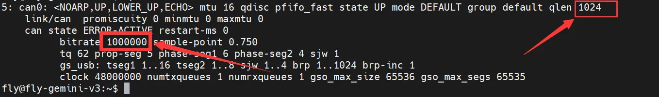
Check CAN status:
ip -details link show can0
- The circled area in the image below shows the host computer's CAN rate and buffer
- The upper
1024is the current CAN0 buffer - The lower
1000000is the current CAN0 rate
Search for devices:
- Fly-Armbian and Standard Host Search Command
- Fly-FAST Search Command
~/klippy-env/bin/python ~/klipper/scripts/canbus_query.py can0
python ~/klipper/scripts/canbus_query.py can0
Normally it will display: Found canbus_uuid=xxxx...
Common Error Solutions
| Error Message | Cause | Solution |
|---|---|---|
OSError: [Errno 19] No such device | CAN device not found | 1. Check USB connection 2. Confirm firmware is correct 3. Execute lsusb to verify |
can.CanError: Failed to transmit: [Errno 100] Network is down | CAN network not configured | 1. Execute the configuration steps above 2. Reboot the system |
can.CanError: Failed to transmit: [Errno 105] No buffer space available | Insufficient buffer | 1. Confirm CAN buffer is 10242. Reboot the system |
Steps to Check if CAN ID is Not Found
Step 1: Basic Checks
- Execute
lsusband see1d50:606f - Both CAN device and tool board are powered on
- Data cable is securely connected
Step 2: Configuration Checks
- CAN network is correctly configured
- Host computer CAN rate matches the tool board firmware rate (default 1M)
- System has been rebooted
Step 3: Hardware Checks
- Both ends of the CAN bus have 120Ω termination resistors
- Power off and measure resistance between CAN-H and CAN-L ≈ 60Ω
- Check for broken wires
- CAN-H and CAN-L are not swapped
Step 4: Special Case Handling
-
If Klipper already occupies the ID:
- Disable the corresponding configuration in Klipper
- Power off completely for 1 minute
- Power on and search again
-
Termination resistor measurement values:
- ≈60Ω: Normal
- ≈120Ω: Only one end has a resistor
- ≈40Ω: Three ends have resistors
- ≈140Ω: Possibly wires are swapped
Quick Troubleshooting Order
- Check device first:
lsusb→ Is1d50:606fpresent? - Check configuration next:
ip -details link show can0→ Is the rate correct? - Check hardware last: Power off and measure resistance → Is it approx. 60Ω?
If still not working after all checks: Try replacing the data cable or device, or contact technical support.
Tool Board Firmware Update Steps
Step 1: Preparation
- Compile the new firmware file as per the tutorial
- Stop the Klipper service:
sudo systemctl stop klipper
Step 2: Obtain the Tool Board ID
Find the corresponding tool board's CAN UUID in the Klipper configuration file (e.g., 241696050c56)
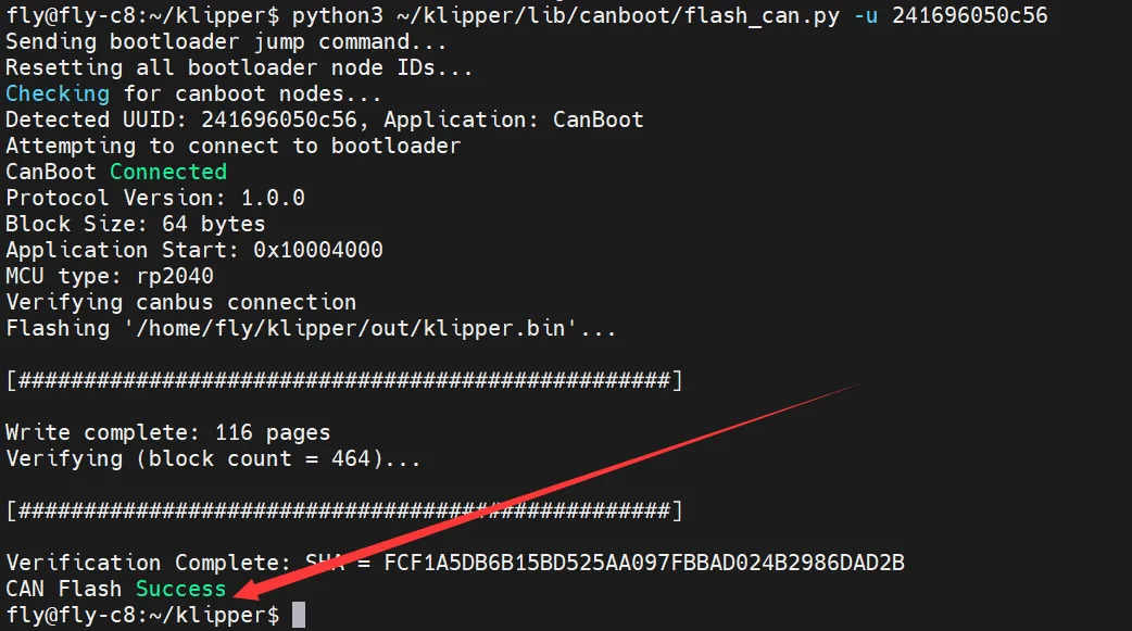
Step 3: Execute Firmware Update
Use the following command to flash the firmware (replace 241696050c56 with your actual CAN UUID):
python3 ~/klipper/lib/canboot/flash_can.py -u 241696050c56
Step 4: Verify Result
- See
CAN Flash Successprompt → Flashing successful - See other error messages → Flashing failed, please check UUID and connection
Note: There must be a space after
-u, followed by your tool board's CAN UUID
Step 5: Restart Service
sudo systemctl start klipper
Update Complete!