Wiring and Configuration
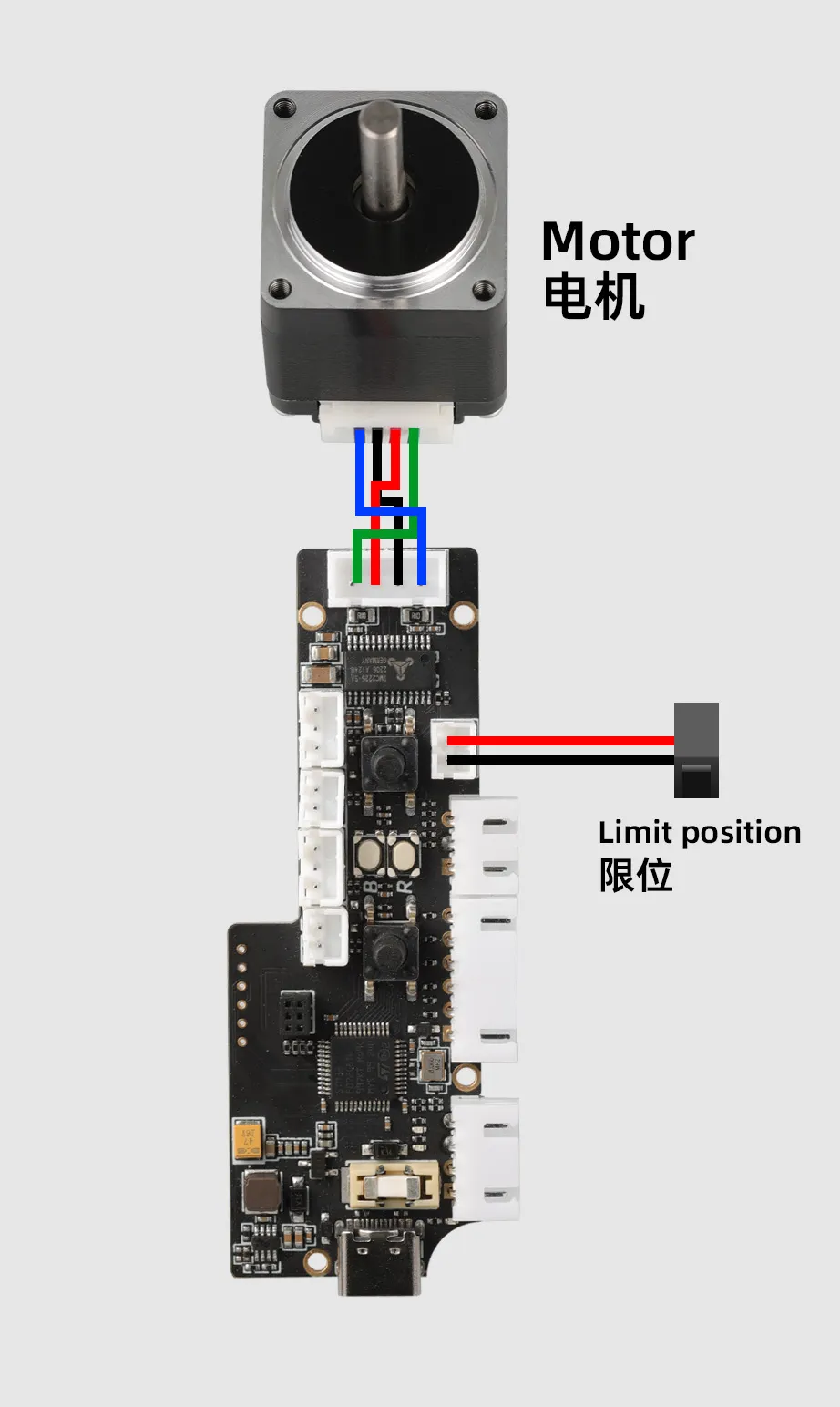
Buffer Internal Wiring Diagram
Installation Video
Buffer Connection to Mainboard and Configuration Methods
- Basic Functions
- Using Trigger to Feed or Retract
- Wiring and Configuration with MDM Sensor
-
This buffer integrates filament runout detection and manual control functions:
-
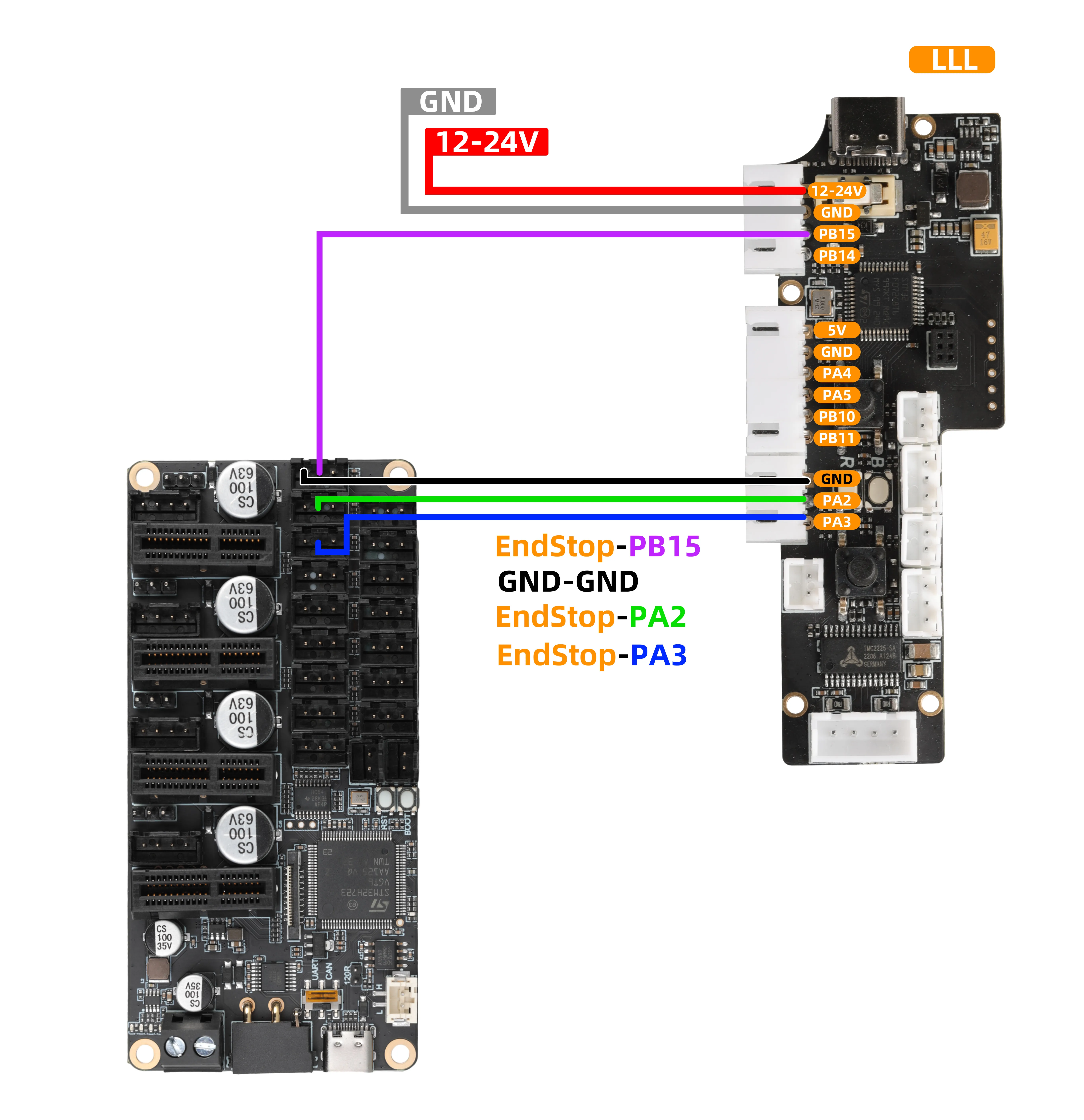
Filament Detection (FILAMENT_SENSOR)
- Signal Output: After filament runout is triggered, the
PB15pin of the buffer outputs a low-level signal.
- Signal Output: After filament runout is triggered, the
-
Feed Button (FEED)
- Single Press: The
PA2pin of the buffer outputs a 3S high-level pulse signal. - Long Press: The buffer will perform continuous feeding until the button is released.
- Single Press: The
-
Retract Button (RETRACT)
- Single Press: The
PA3pin of the buffer outputs a 3S low-level pulse signal. - Long Press: The buffer will perform continuous retraction until the button is released.
- Single Press: The
Wiring Guide
-
When using the above functions, please refer to the wiring diagram below:
- The
MMU tool boardin the diagram is only for reference of interface definition. When using it in practice, you need to:
- Directly connect the cables to the endstop signal ports of your mainboard (e.g., Klipper, Marlin mainboard).
- In the configuration file (e.g.,
printer.cfg), modify and confirm the port number configuration corresponding toPD3,PD4, andPD5to ensure proper functionality.
Configuration Reference
[mcu LLL_PLUS]
serial:/dev/serial/by-id/usb-Klipper_stm32h723xx_12345-if00

[filament_switch_sensor Material_breakage_detection]
pause_on_runout: true
switch_pin: ^LLL_PLUS:PD3
runout_gcode:
    PAUSE
    RESPOND MSG="material shortage"
insert_gcode:
    RESPOND MSG="Detected"
event_delay: 1.0
pause_delay: 0.5

[gcode_button Load_consumables]
pin:^LLL_PLUS:PD4 # Replace with your own pin, connected to the feed pin
press_gcode:
    _Load_consumables

[gcode_button RETRACT]
pin:^!LLL_PLUS:PD5 # Replace with your own pin, connected to the retract pin
press_gcode:
    _RETRACT

[gcode_macro CONFIG]
description: Extruder configuration
variable_extruder_temp: 200    ## Temperature
variable_extruder_length: 50   ## Length
variable_extruder_speed: 5    ## Speed (mm/s)
gcode:

[gcode_macro _Load_consumables]  ## Feed
gcode:
    {% set temp = printer["gcode_macro CONFIG"].extruder_temp %}
    {% set length = printer["gcode_macro CONFIG"].extruder_length %}
    {% set speed = printer["gcode_macro CONFIG"].extruder_speed %}
    {% set feedrate = speed * 60 %}

    RESPOND MSG="Heat the extruder to {temp} °C"
    RESPOND MSG="Heating extruder to {temp} °C"
    M109 S{temp}

    RESPOND MSG="Start feeding {length}mm"
    RESPOND MSG="Starting feed of {length}mm"
    G91  ; Relative coordinate mode
    G1 E{length} F{feedrate}
    G90  ; Absolute coordinate mode

    RESPOND MSG="Extrusion completed"
    RESPOND MSG="Extrusion completed"
    M104 S0

[gcode_macro _RETRACT]  ## Retract
gcode:
    {% set temp = printer["gcode_macro CONFIG"].extruder_temp %}
    {% set length = printer["gcode_macro CONFIG"].extruder_length %}
    {% set speed = printer["gcode_macro CONFIG"].extruder_speed %}
    {% set feedrate = speed * 60 %}

    RESPOND MSG="Heat the extruder to {temp} °C"
    RESPOND MSG="Heating extruder to {temp} °C"
    M109 S{temp}

    RESPOND MSG="Start material return {length}mm"
    RESPOND MSG="Starting retraction of {length}mm"
    G91  ; Relative coordinate mode
    G1 E-{length} F{feedrate}
    G90  ; Absolute coordinate mode

    RESPOND MSG="Return of materials completed"
    RESPOND MSG="Material return completed"
    M104 S0
-
Firmware must be updated to
V1.1.0 -
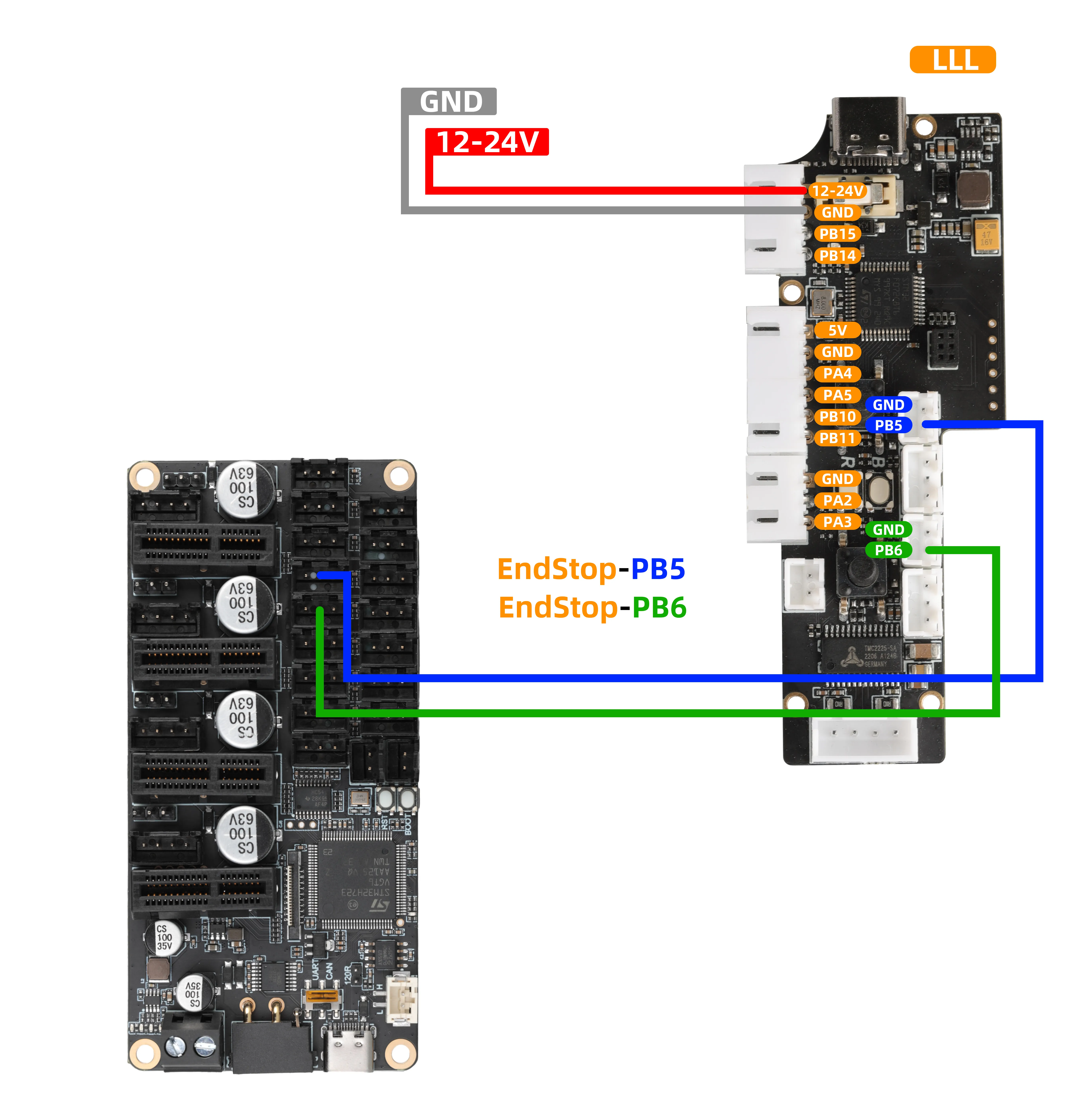
The buffer can achieve automatic continuous feeding by detecting the following pin level states:
-
Automatic Feeding: When a low-level signal is detected on pin
PB5, the buffer will perform continuous feeding. -
Automatic Retraction: When a low-level signal is detected on pin
PB6, the buffer will perform continuous retraction.
Wiring Guide
- When using the above functions, please refer to the wiring diagram below:
- The
MMU tool boardin the diagram is only for reference of interface definition. When using it in practice, you need to:
- Directly connect the cables to the endstop signal ports of your mainboard (e.g., Klipper, Marlin mainboard).
- In the configuration file (e.g.,
printer.cfg), modify and confirm the port number configuration corresponding toPB5andPB6to ensure proper functionality.
Reference Configuration
- Add configuration
- Please note that this configuration should be added after the basic functions are configured
[output_pin _feeding]
pin:LLL_PLUS:PD6
shutdown_value: 0
value:0

[output_pin _material_return]
pin:LLL_PLUS:PD7
shutdown_value: 0
value:0

[gcode_macro Buffer_feeding]  ## Buffer feeding
gcode:
    {% set temp = printer["gcode_macro CONFIG"].extruder_temp %}
    {% set length = printer["gcode_macro CONFIG"].extruder_length %}
    {% set speed = printer["gcode_macro CONFIG"].extruder_speed %}
    {% set feedrate = speed * 60 %}

    RESPOND MSG="Heat the extruder to {temp} °C"
    RESPOND MSG="Heating extruder to {temp} °C"
    M109 S{temp}

    RESPOND MSG="Start feeding {length}mm"
    RESPOND MSG="Starting feed of {length}mm"
    SET_PIN PIN=_feeding VALUE=1
    G91  ; Relative coordinate mode
    G1 E{length} F{feedrate}
    G90  ; Absolute coordinate mode


    RESPOND MSG="Extrusion completed"
    RESPOND MSG="Extrusion completed"
    SET_PIN PIN=_feeding VALUE=0
    M104 S0

[gcode_macro RBuffer_material_return]  ## Buffer retraction
gcode:
    {% set temp = printer["gcode_macro CONFIG"].extruder_temp %}
    {% set length = printer["gcode_macro CONFIG"].extruder_length %}
    {% set speed = printer["gcode_macro CONFIG"].extruder_speed %}
    {% set feedrate = speed * 60 %}

    RESPOND MSG="Heat the extruder to {temp} °C"
    RESPOND MSG="Heating extruder to {temp} °C"
    M109 S{temp}

    RESPOND MSG="Start material return {length}mm"
    RESPOND MSG="Starting retraction of {length}mm"
    SET_PIN PIN=_material_return VALUE=1
    G91  ; Relative coordinate mode
    G1 E-{length} F{feedrate}
    G90  ; Absolute coordinate mode
    SET_PIN PIN=_material_return VALUE=0

    RESPOND MSG="Return of materials completed"
    RESPOND MSG="Material return completed"
    M104 S0
Function Overview
- When used with the
FLY-MDMfilament runout/clog sensor, the buffer can detect clogging - Firmware must be updated to
V1.1.0
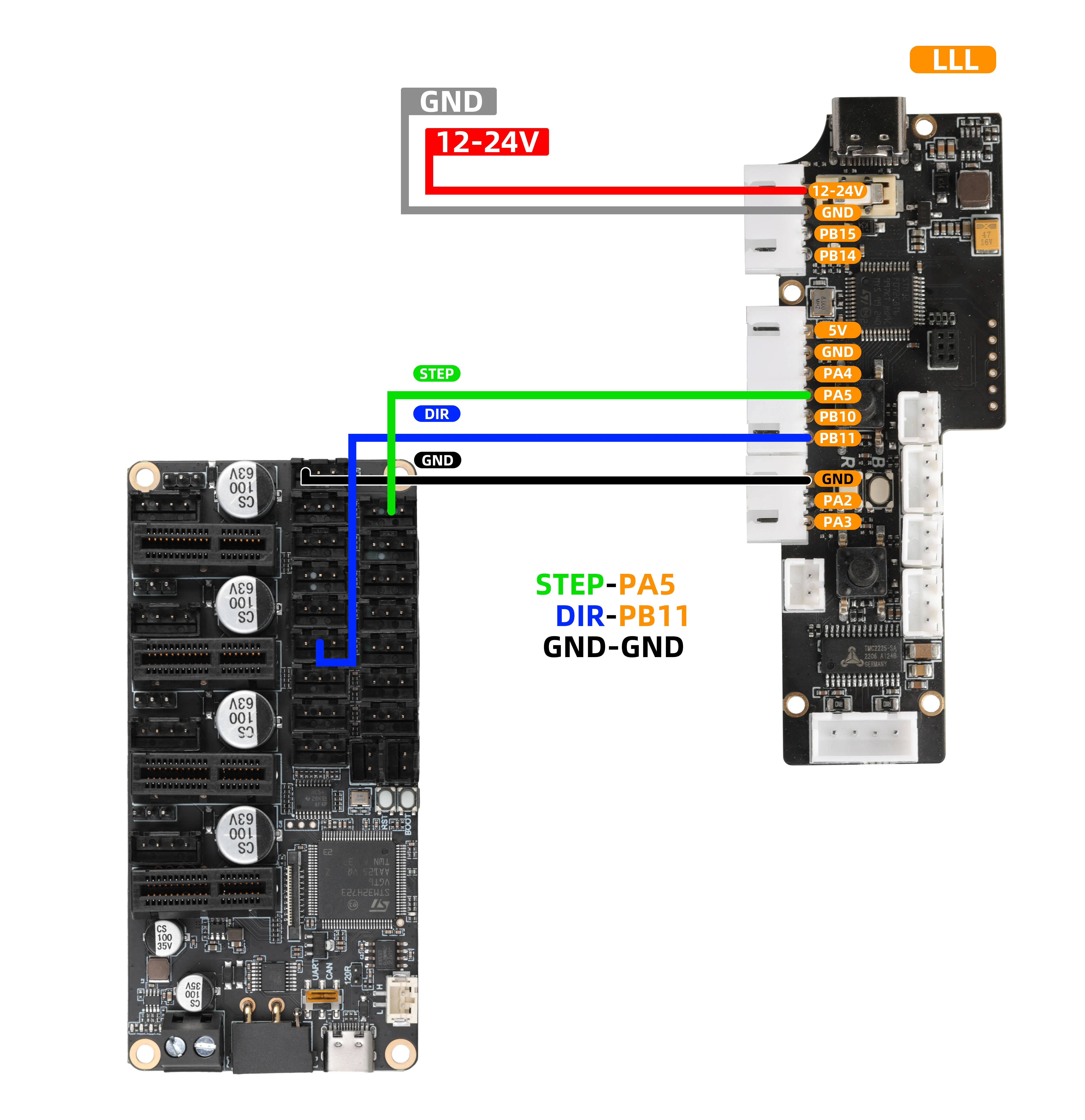
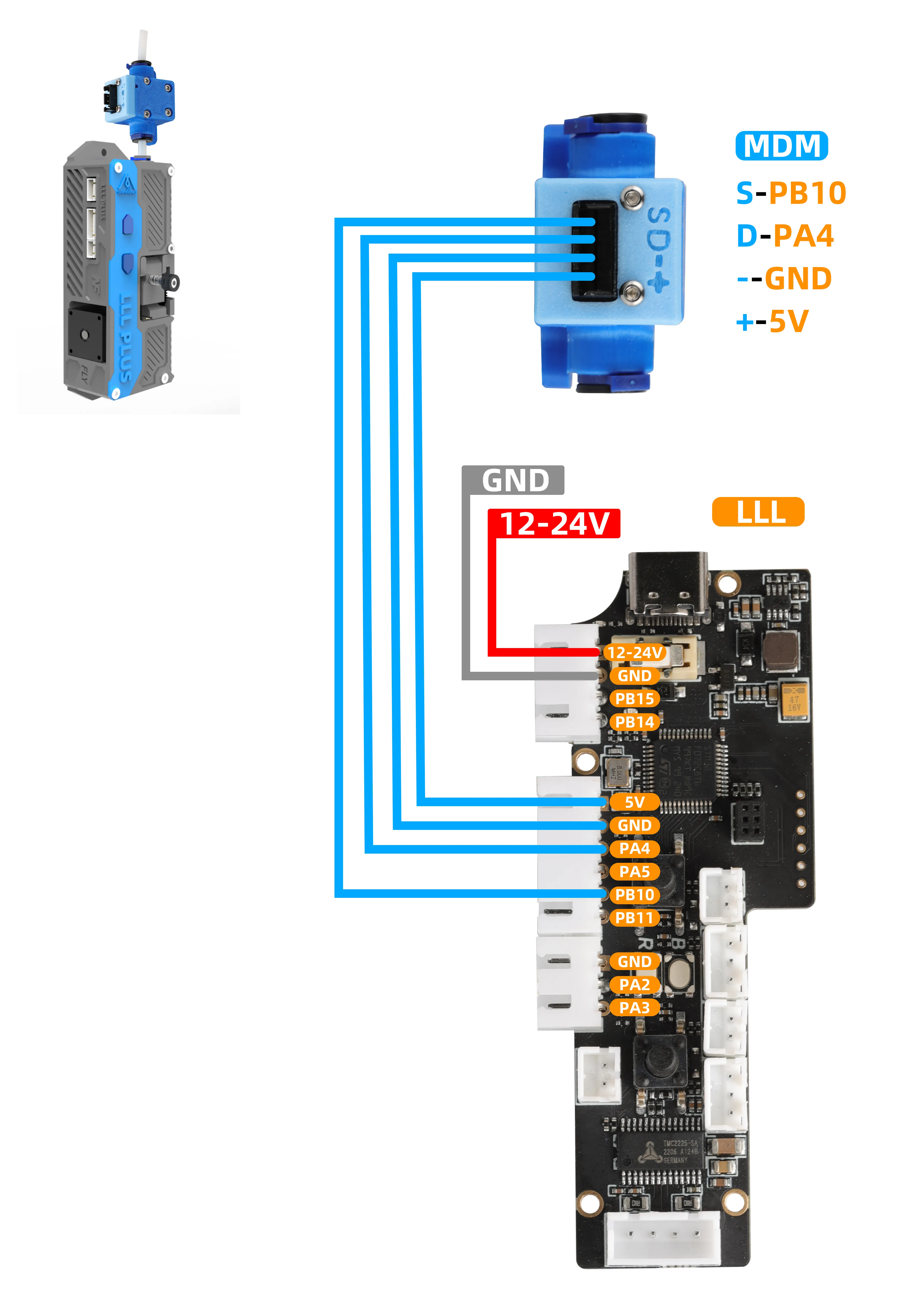
Hardware Wiring
- The signal lines of the buffer should be connected to any unused general-purpose digital output pin on the mainboard, for example:
- Connect the
STEPpin from the buffer'sPA5to one of the mainboard'sPWM,RGB, or12864pins. Note that the servo port of the BL-Touch can also be used. - Connect the
DIRpin from the buffer'sPB11to a limit switch port on the mainboard.
-
This connection is used to monitor the working status of the extruder motor, which is key to implementing clog detection.
-
When using the above functions, please refer to the wiring diagram below:
- The
MMU tool boardin the diagram is only for reference of interface definition. When using it in practice, you need to:
- Directly connect the cables to the endstop signal ports of your mainboard (e.g., Klipper, Marlin mainboard).
- In the configuration file (e.g.,
printer.cfg), modify and confirm the port number configuration corresponding toPD3andPC0to ensure proper functionality.
- MDM Reference Wiring
Reference Configuration
- Add configuration
- Please note that this configuration should be added after the basic functions are configured
- Please note that in the configuration below, you need to modify the
STEPandDIRpins to match your wiring - Also, other configurations should match your extruder configuration, otherwise clog detection may fail
[extruder_stepper my_extra_stepper]
extruder = extruder
step_pin: LLL_PLUS:PE10
dir_pin: LLL_PLUS:PD4
rotation_distance: 17.472
gear_ratio:50:10
microsteps:16
full_steps_per_rotation: 200
Buffer Parameter Configuration
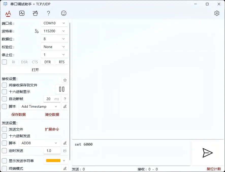
Get Serial Tool Assistant- Use a
USBcable to connect the module to your computer. Open the serial tool assistant, select the corresponding COM port, set the baud rate to 115200, then click Connect.
- If your extruder configuration does not include
gear_ratio, set bothDriving Gear TeethandDriven Gear Teethto1
Parameter Description
| Function | Configuration Command (Please enter in the serial tool) | Default | Unit | Notes |
|---|---|---|---|---|
| View all current parameters | Loading... | - | - | Send the command to read all current configurations. |
| Set motor pulse count | Loading... | 916 | - | Sets the number of pulses required for the motor to move one millimeter. |
| Set encoder detection distance | Loading... | 1.73 | mm | Sets the filament movement distance represented by each encoder signal. |
| Set running timeout duration | Loading... | 60000 | ms | Sets the auto-stop time in an untriggered state to prevent continuous extrusion. |
| Set error scaling factor | Loading... | 2.0 | - | Allowed error = encoder value × scale value.Example: 1.73 * 2.0 = 3.46 mm |
Operation Notes:
- Command Format: In the "Configuration Command" column above, the entire line of command (e.g.,
steps 916) must be entered completely. - Sending Method: Enter the command into the sending area of the serial assistant, then click Send.
- Auto Save: After successfully sending the command, the parameters will take effect immediately and be automatically saved, no additional save operation is required.
- Confirm Configuration: After modifying any parameter, send the
infocommand to query all current parameters and verify if the configuration is correct.