USB Firmware Compilation
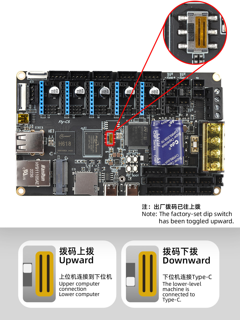
Check DIP Switch
- During normal operation, please set the switch to the
upposition - When toggling the switch, please push it all the way
up, otherwise the connection to the microcontroller may fail!!!
SSH into the Host Machine
- Before compiling the firmware, you must connect to the host machine via
Wi-Fi SSH
- Please first: Connect to the host machine SSH via Wi-Fi
- USB Firmware Flashing
- Compile USB Firmware Manually
USB Firmware Flashing
- A USB firmware has already been pre-compiled in the FLYOS-FAST system. There is no need to manually compile the firmware; simply execute the command below to flash it
- Alternatively, you can choose to
compile the USB firmware manually
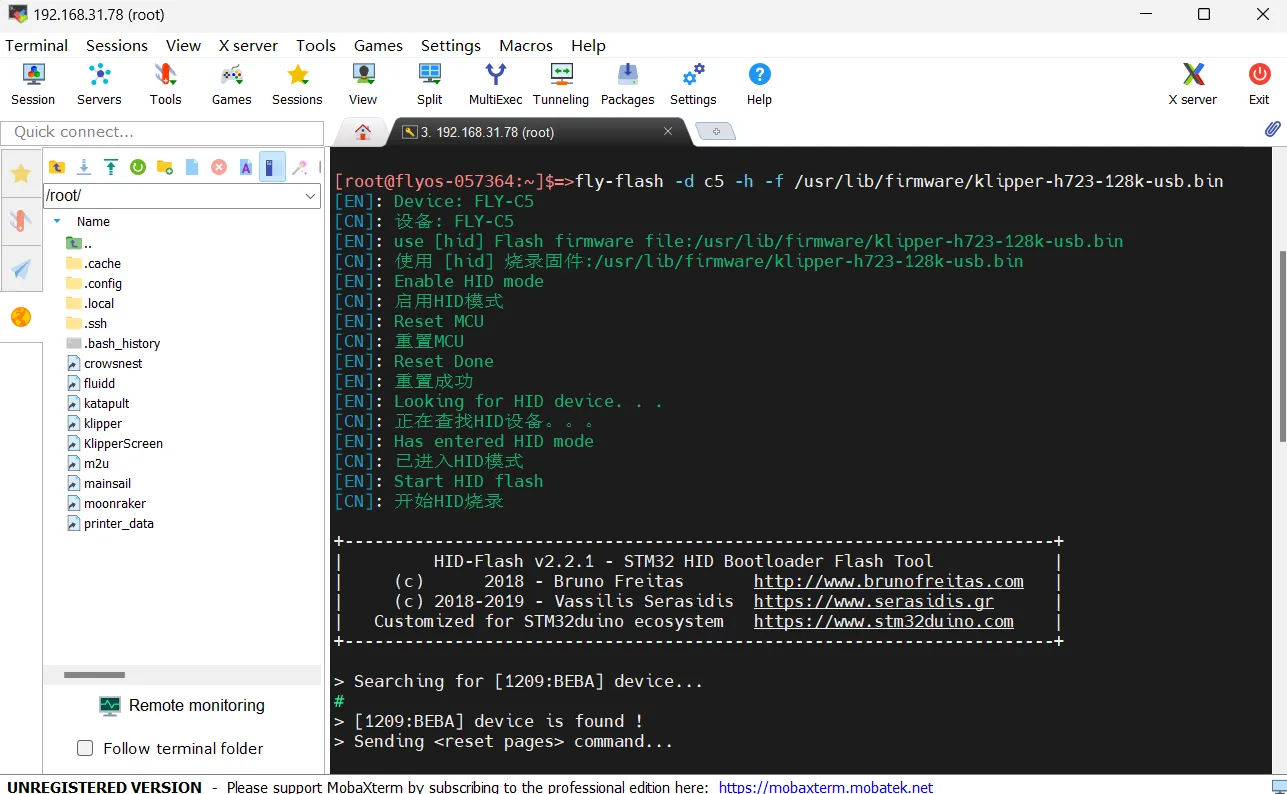
- Connect to the host machine via SSH and enter the command below
fly-flash -d auto -h -f /usr/lib/firmware/klipper/stm32h723-128k-usb.bin
Compile USB Firmware Manually
Klipper Firmware Compilation and Configuration Page Operation Instructions
Please ensure that the keyboard input method is in half-width mode, i.e., English mode.
- The up arrow key
↑, down arrow key↓are used to move the cursor up and down to select menu items. - The confirm key
Enteror space keySpaceis used to check the menu or enter a sub-menu. - The exit key
ESCis used to return to the previous menu. - The
Qkey is used to exit the Klipper firmware configuration page. - The
Ykey, when exiting the Klipper firmware configuration page and there is a prompt, click theYkey to save the configuration file.
If there are fewer options in the configuration page, please first check [ ] Enable extra low-level configuration options to display some hidden options.
Below is an introduction on how to compile the firmware:
-
After connecting to SSH, enter the following command and press Enter:
cd ~/klipper && rm -rf ~/klipper/.config && rm -rf ~/klipper/out && make menuconfig -
Where
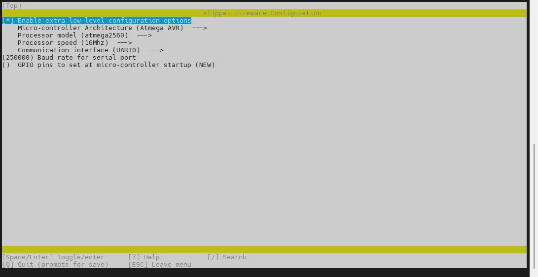
rm -rf ~/klipper/.config && rm -rf ~/klipper/outis to delete previous compilation data and firmware,make menuconfigis to compile the firmware, after execution, the following interface should appear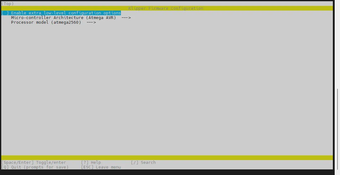
-
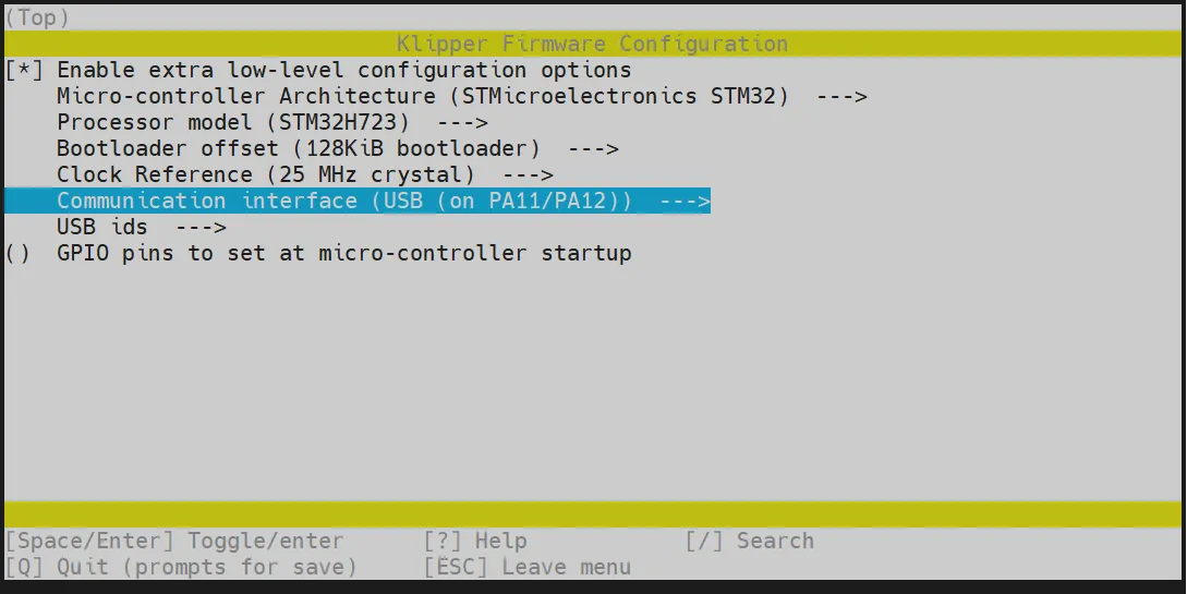
Select Enable extra low-level configuration options and press Enter
-
Enter the menu Micro-controller Architecture then select STMicroelectronics STM32 and press Enter
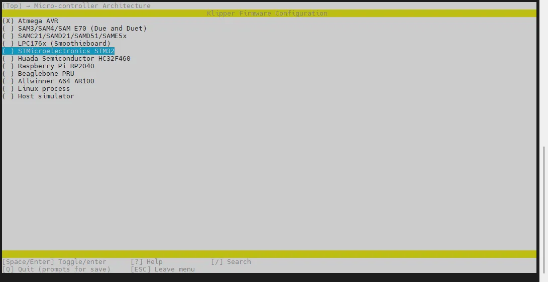
-
Enter the menu Processor model, select STM32H723 and press Enter
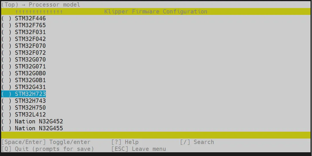
-
Select Bootloader offset, select: 128KiB bootloader
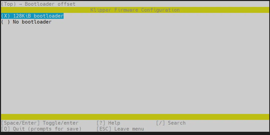
-
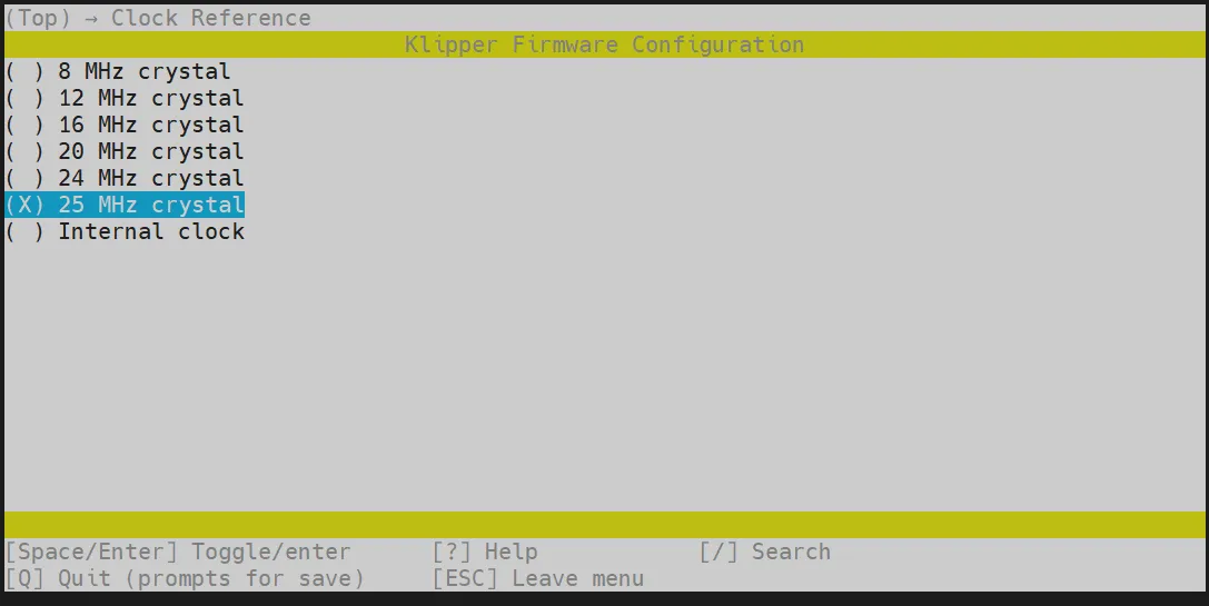
Select Clock Reference (8 MHz crystal), select: 25 MHz crystal
-
Communication interface, select: USB (on PA11/PA12)
- Press the
Qkey, then selectSave configurationand press theYkey

-
Configuration should now be saved, and you will return to the command line interface
-
Enter the following command to begin compilation (this may take some time)
make -j4
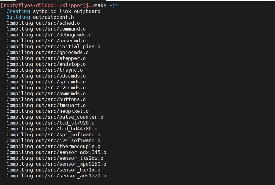
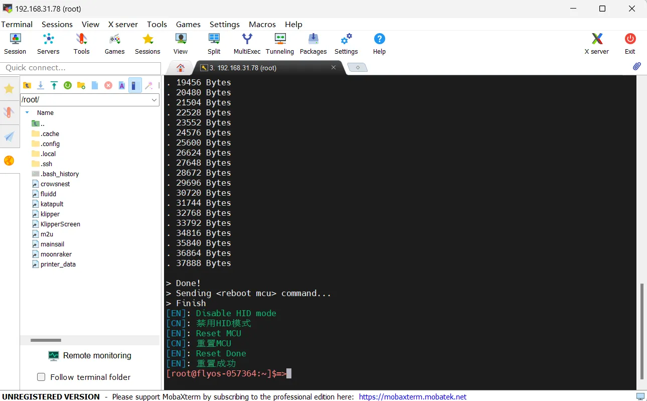
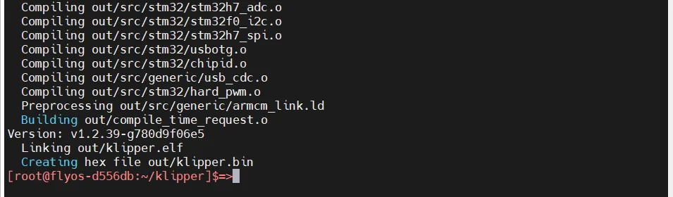
- The final output should look like this if the compilation is successful
Firmware Flashing
Execute the command below to flash the firmware
fly-flash -d auto -h -f /data/klipper/out/klipper.bin
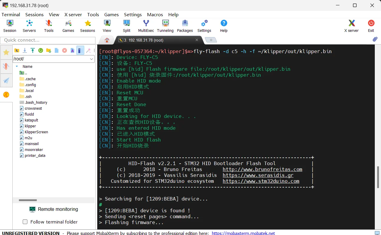
Searching for USB ID
- Open your browser, enter the IP address of the host computer in the address bar. For example, if my host IP is
192.168.101.179, just type it and press Enter.
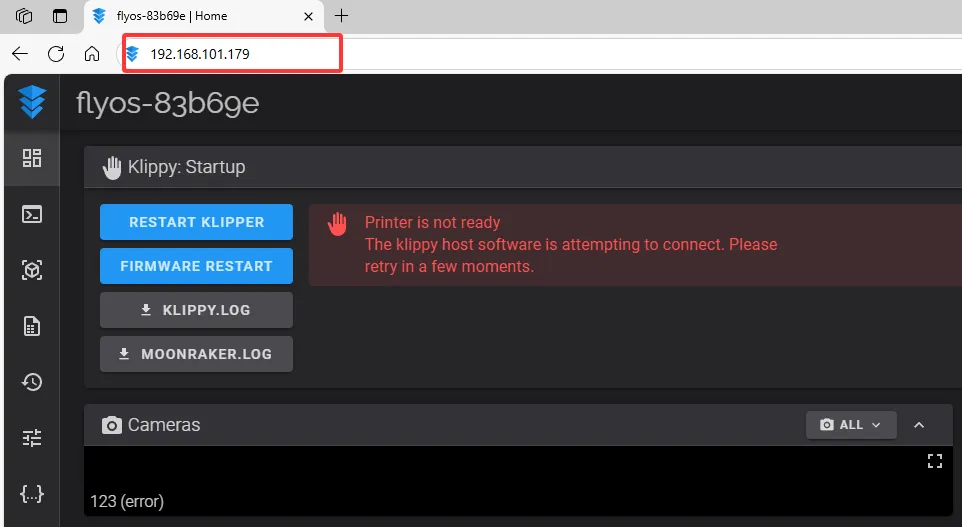
- Open the host's WEB interface. In the left sidebar configuration options, find:
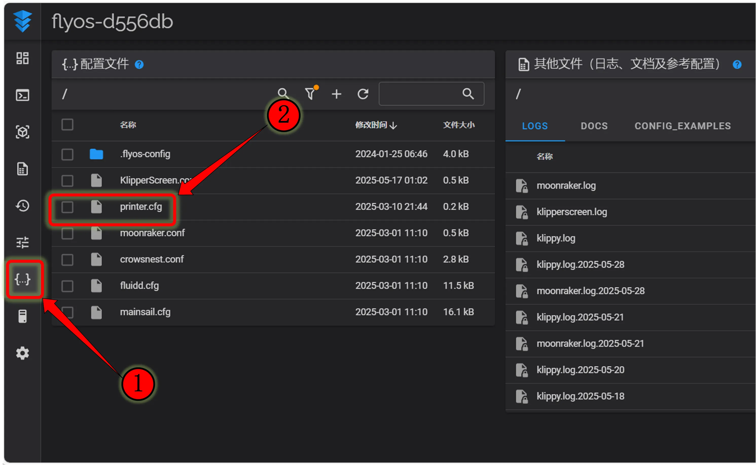 |
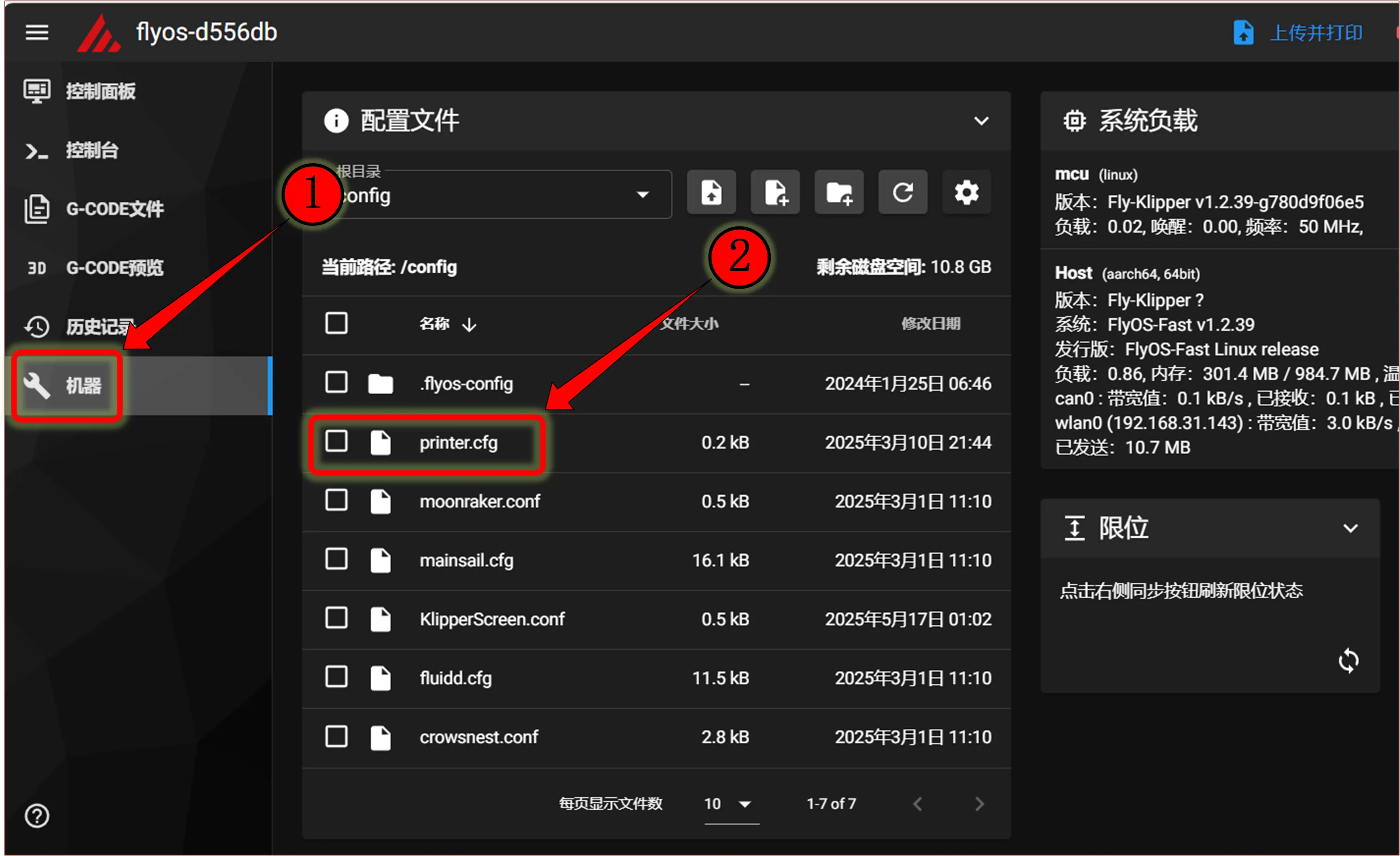 |
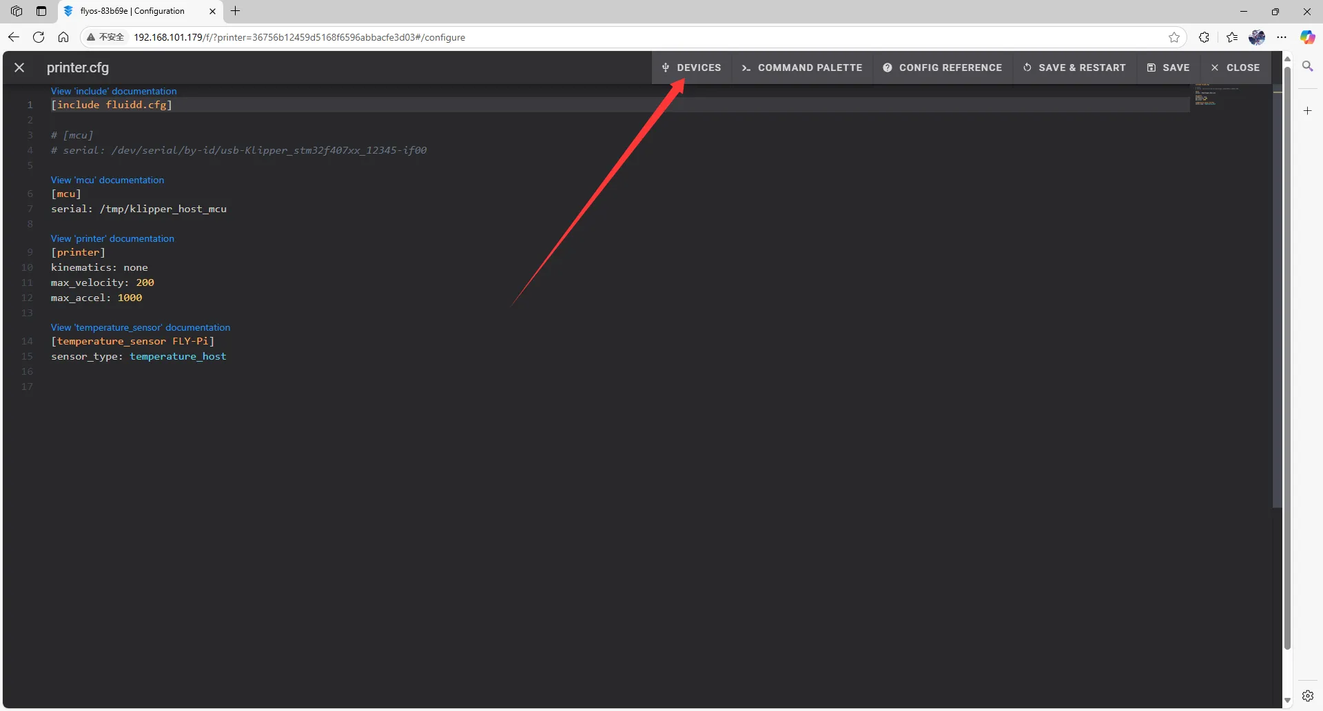
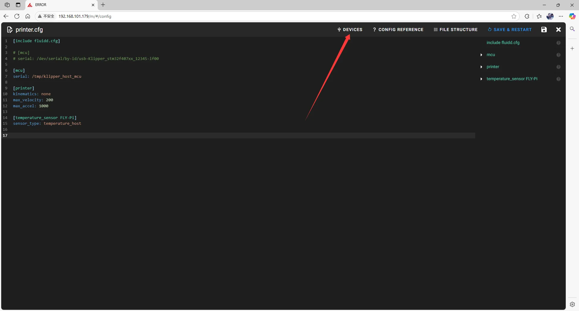
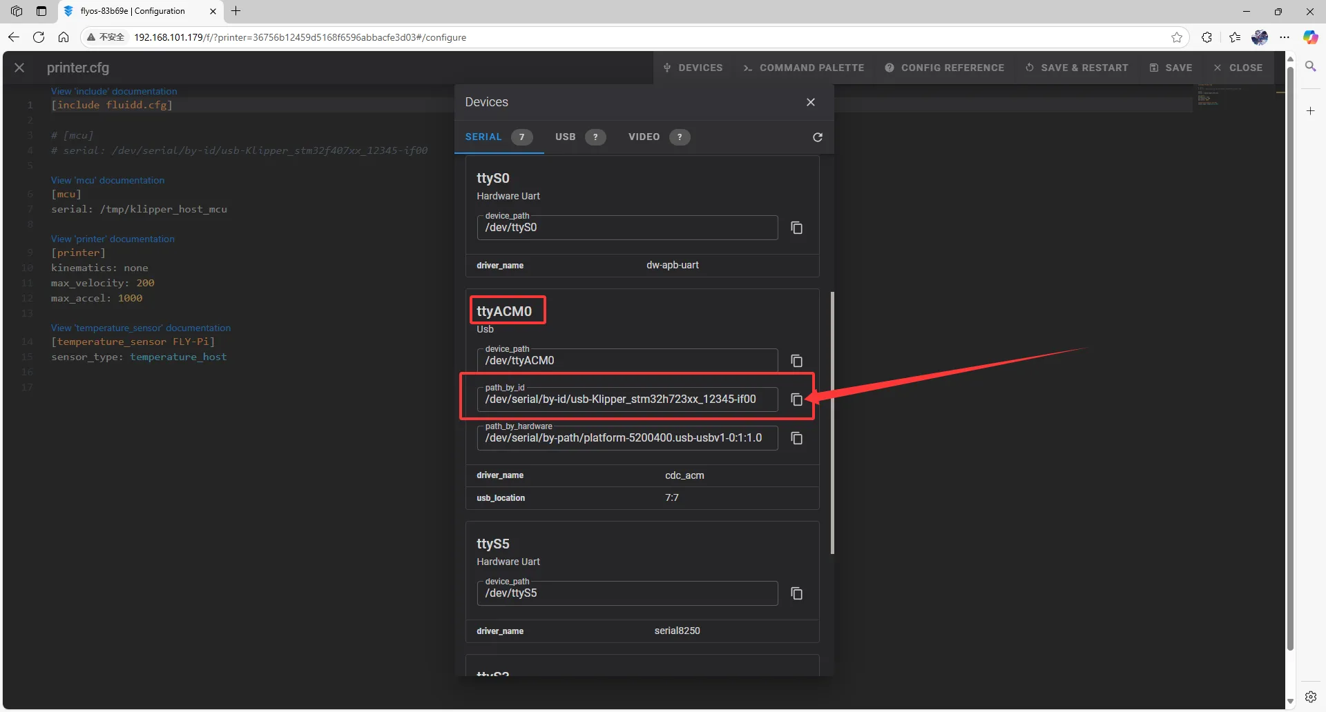
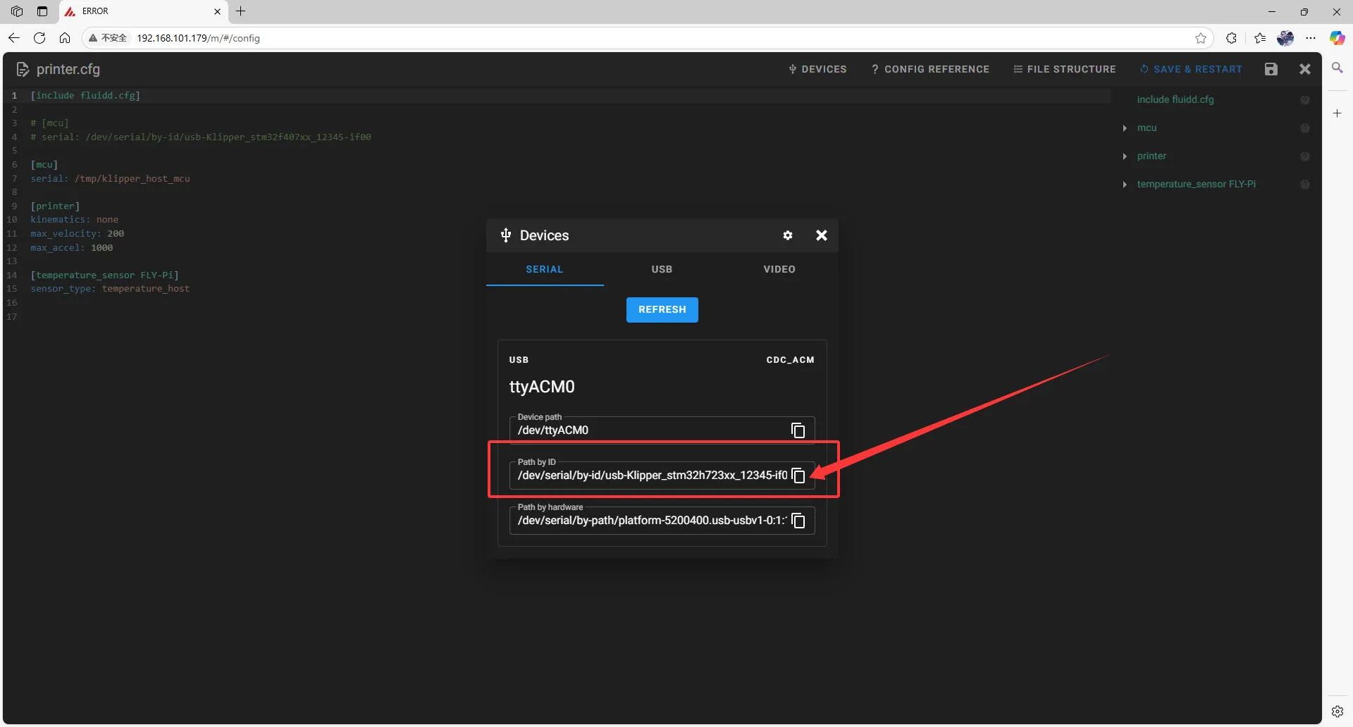
- Click
printer.cfgto enter, then clickDEVICESin the top right corner.
 |  |
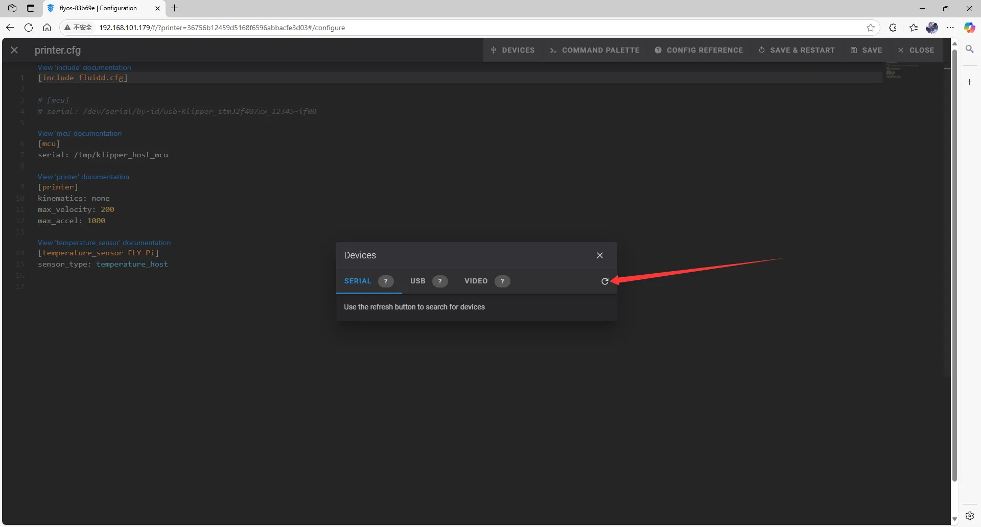
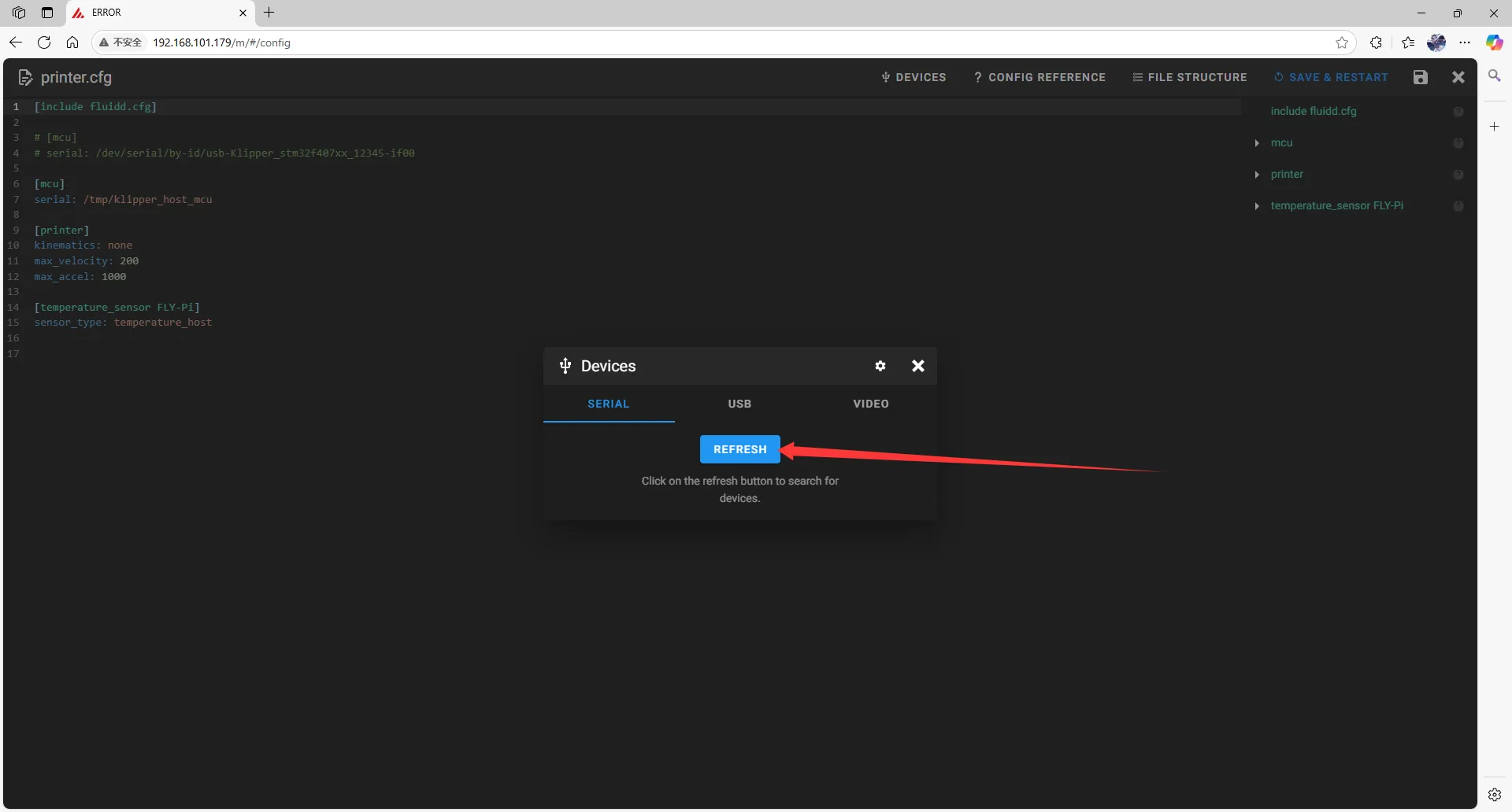
- Click
SERIAL, then refresh.
 |
 |
- Copy the ID. Click where the arrow points to copy.
 |
 |
Filling in the USB ID
Please note, the ID below cannot be used!!!!
serial: /dev/serial/by-id/usb-1a86_USB_Serial-if00-port0
- Close
DEVICESand fill in the ID.
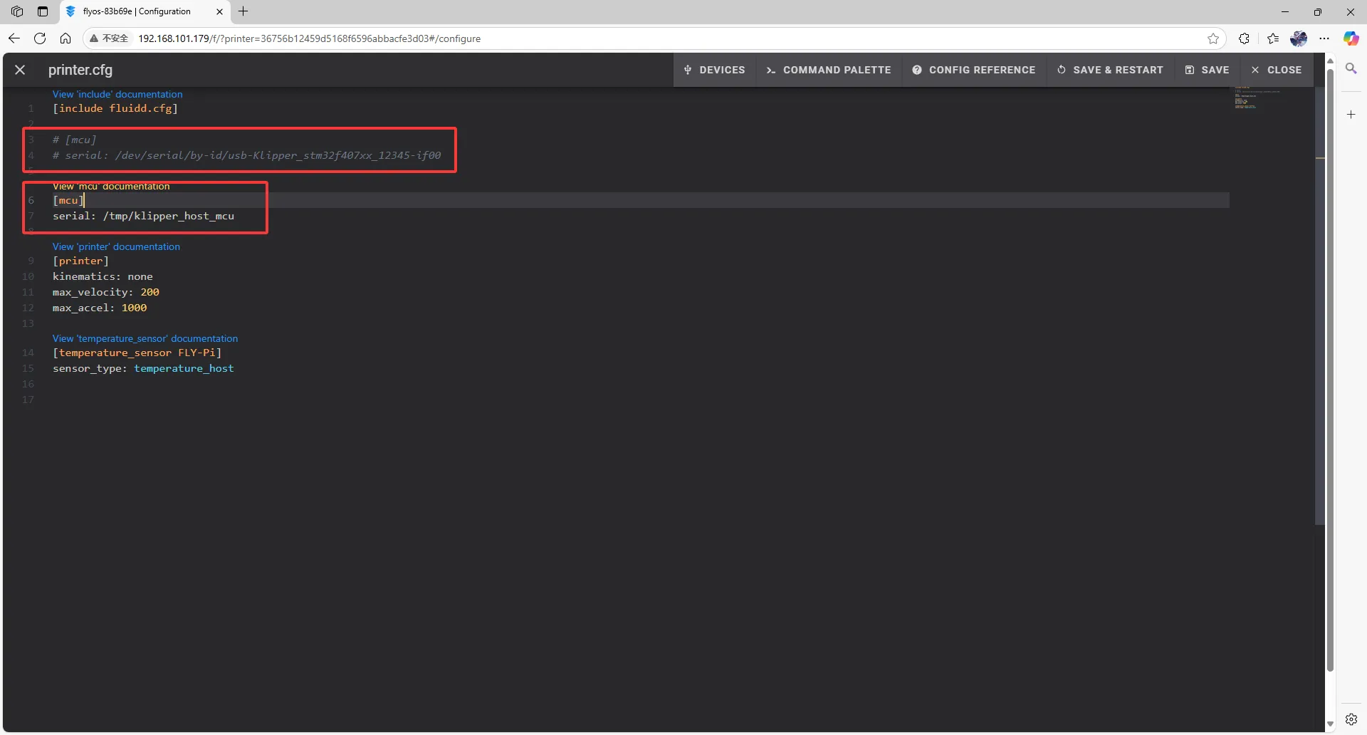
- In the configuration file, change:
[mcu]
serial: /tmp/klipper_host_mcu
to:
[mcu host]
serial: /tmp/klipper_host_mcu
- Add:
[mcu]
serial: <Replace this with the ID you just queried>
 |
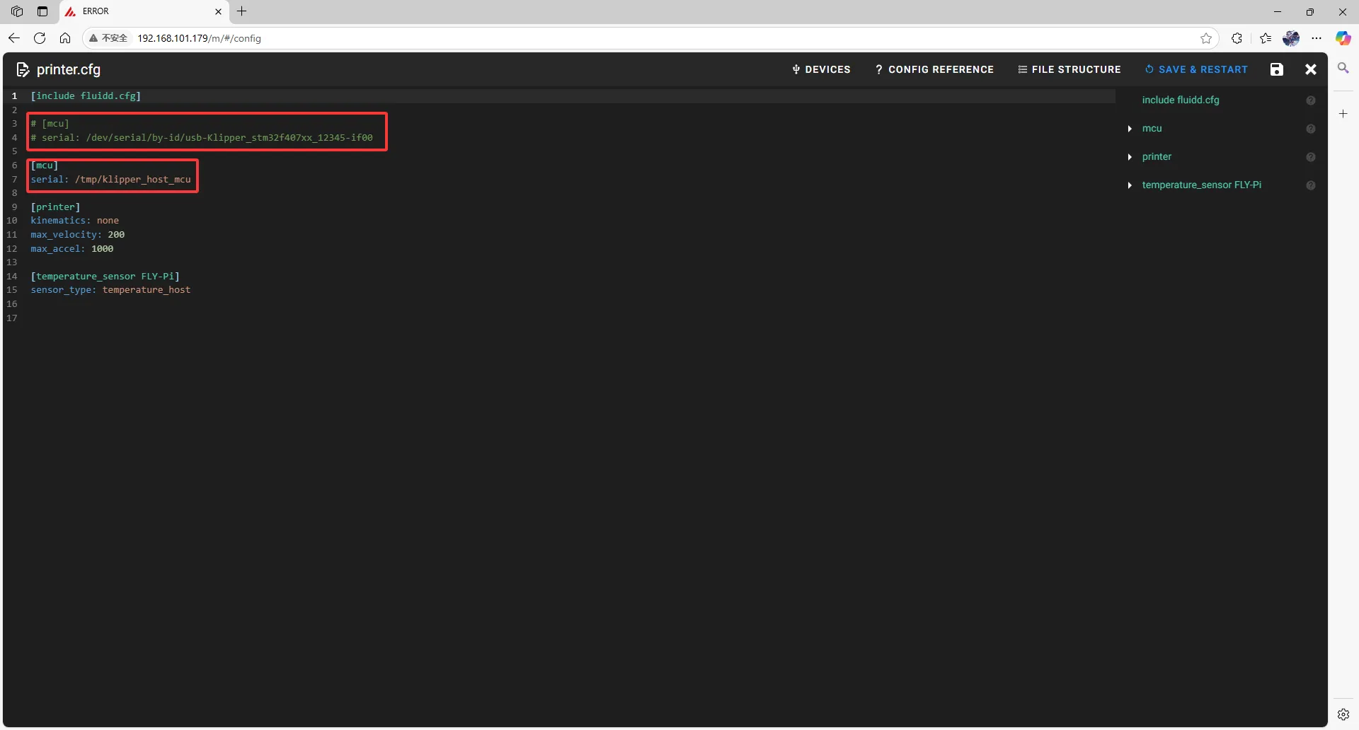 |
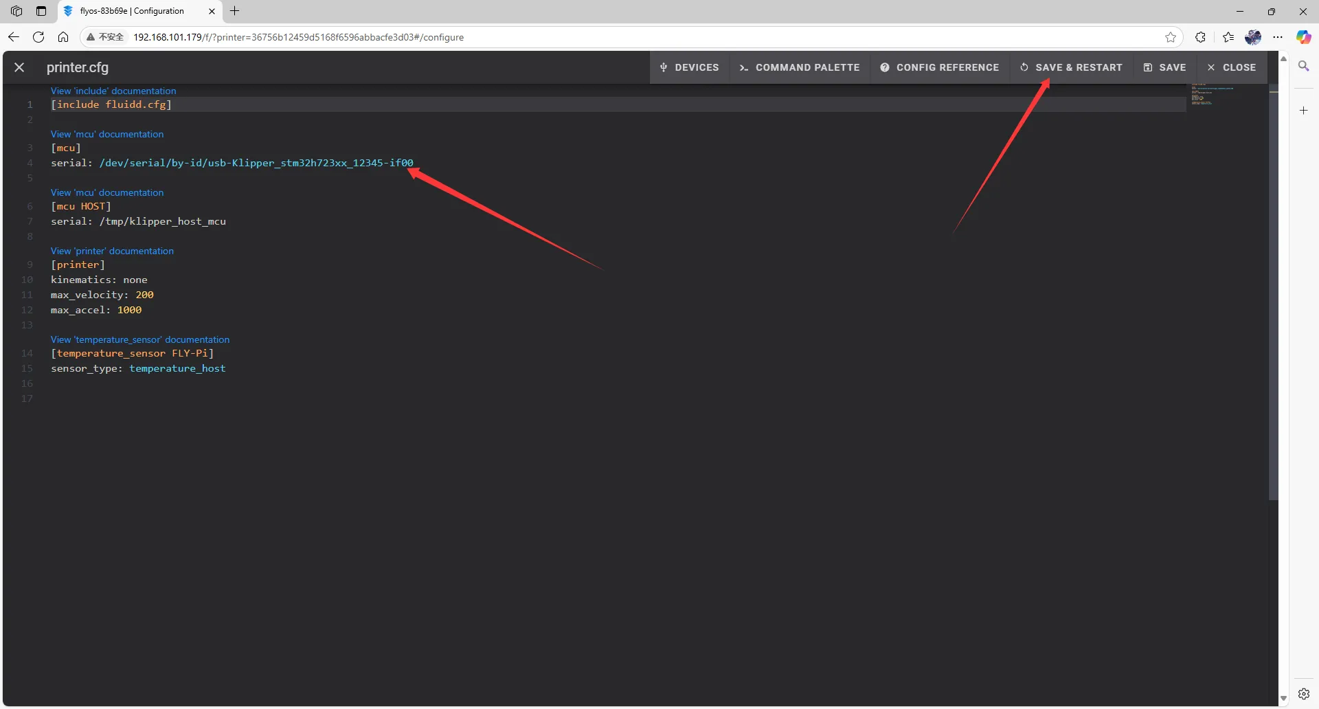
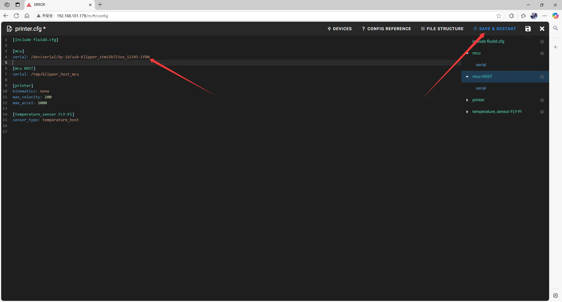
- Fill the ID into the configuration.
- After filling in the ID, click
SAVE & RESTARTin the top right corner.
 |  |
- If Klipper prompts
ADC out of range, this is normal. Connect the heated bed and thermistor to the mainboard, configure the thermistor pins for the hotend and heated bed, then save and restart.
Note: All IDs appearing in this document are examples. The actual ID for each mainboard is different. Please fill in the ID you actually obtained.