Introduction
The apls pressure module is a pressure sensing solution designed based on ADS131M02, specifically developed for automatic Z-axis homing and mesh bed leveling of 3D printers. Through high-sensitivity pressure detection and real-time signal processing, the module can accurately perceive the contact status between the print head and the bed, achieving millimeter-level leveling accuracy, eliminating errors from traditional mechanical limit calibration, and significantly improving the first-layer printing success rate.
Usage of apls Pressure Module
Recommended to Pair with Wiping Functionality
When using the apls pressure module, it is recommended to pair it with the wiping function to ensure the cleanliness of the nozzle, thereby improving the precision and stability of leveling.
XH2.54 4Pin Wiring Diagram
The module can be directly inserted into the mainboard UART interface or connected to the UART interface of the expansion board. If there is no UART interface, two pins can be found on the mainboard, paying attention to the positive and negative poles of the power line.
Installation Precautions
- Ensure that the module is installed securely to avoid poor contact due to vibration during printing.
- Check whether the wiring is correct to avoid the module failing to work properly due to incorrect wiring.
- Before the first use, it is recommended to conduct multiple leveling tests to ensure that the sensitivity and accuracy of the module meet expectations.
Status Light Display
- Power-On State: The green status light in the red frame remains lit, indicating that the module is working normally.
- Trigger State: The red frame status light goes out, indicating that the module is in the trigger state.
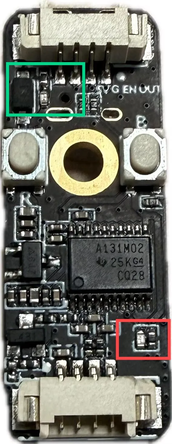
Status Light Troubleshooting
- If the status light does not light up, check whether the power connection is correct.
- If the status light keeps flashing, it may indicate that the module detects an abnormal signal; please check whether the probe is jammed or damaged by foreign objects.
Configuration Guide
Replace the probe and homing parts in the existing configuration file with the following configuration:
Example Configuration File
The following is the recommended configuration file content, which should be adjusted according to actual needs:
[homing_override]
axes: xyz
set_position_z:10
gcode:
       G91
       G1 Z10 F3000
       G90
        SET_PIN PIN=_probe_ready VALUE=0
        ## _LIFT_Z
       {% set home_all = 'X' not in params and 'Y' not in params and 'Z' not in params %}

       {% if home_all or 'X' in params %}
            G28 X
       {% endif %}

       {% if home_all or 'Y' in params %}
            G28 Y
            G0 X{printer.toolhead.axis_maximum.x / 2} Y{printer.toolhead.axis_maximum.y / 2} F6000
       {% endif %}

       {% if home_all or 'Z' in params %}
       # If using eddy and pressure sensor together, uncomment the following line
            #SET_PIN PIN=_probe_ready VALUE=1
            G28 Z
            #SET_PIN PIN=_probe_ready VALUE=0
            G1 Z10 F3000
        {% endif %}

[output_pin _probe_ready]
pin: PA9
shutdown_value: 0

[probe]
pin: PA10
x_offset: 0                  # X-axis offset of the sensor relative to the nozzle
y_offset: 0               # Y-axis offset of the sensor relative to the nozzle
z_offset:0                # Z-axis offset of the sensor relative to the nozzle
speed: 8                 # Leveling speed
samples: 3                   # Number of samples
samples_result: median       # Value selection method (default median - median value)
sample_retract_dist: 2     # Retract distance during leveling
samples_tolerance: 0.05      # Sampling tolerance (note that too small a value may increase the number of samples)
samples_tolerance_retries: 3 # Retry times when exceeding tolerance
activate_gcode:
           G4 P500
           SET_PIN PIN=_probe_ready VALUE=1
deactivate_gcode:
           SET_PIN PIN=_probe_ready VALUE=0
Reference for Adjusting Z Offset Value
Use this command to adjust the z-offset:
PROBE_CALIBRATE
- Before adjusting the
z-offsetvalue, refer to the Klipper documentation tutorial: Paper Test
- If you want to use the pressure module as a Z-axis limit switch, replace the original
endstop_pinconfiguration with:endstop_pin: probe:z_virtual_endstop