Onboard USB Port Precautions
Overview
This document explains the USB interface functions, connection methods, and DIP switch configuration for the Fly-D8 mainboard.
Host Computer Connection Instructions
The Fly-D8 mainboard can only communicate with the host computer for Klipper via the Type-C USB interface.
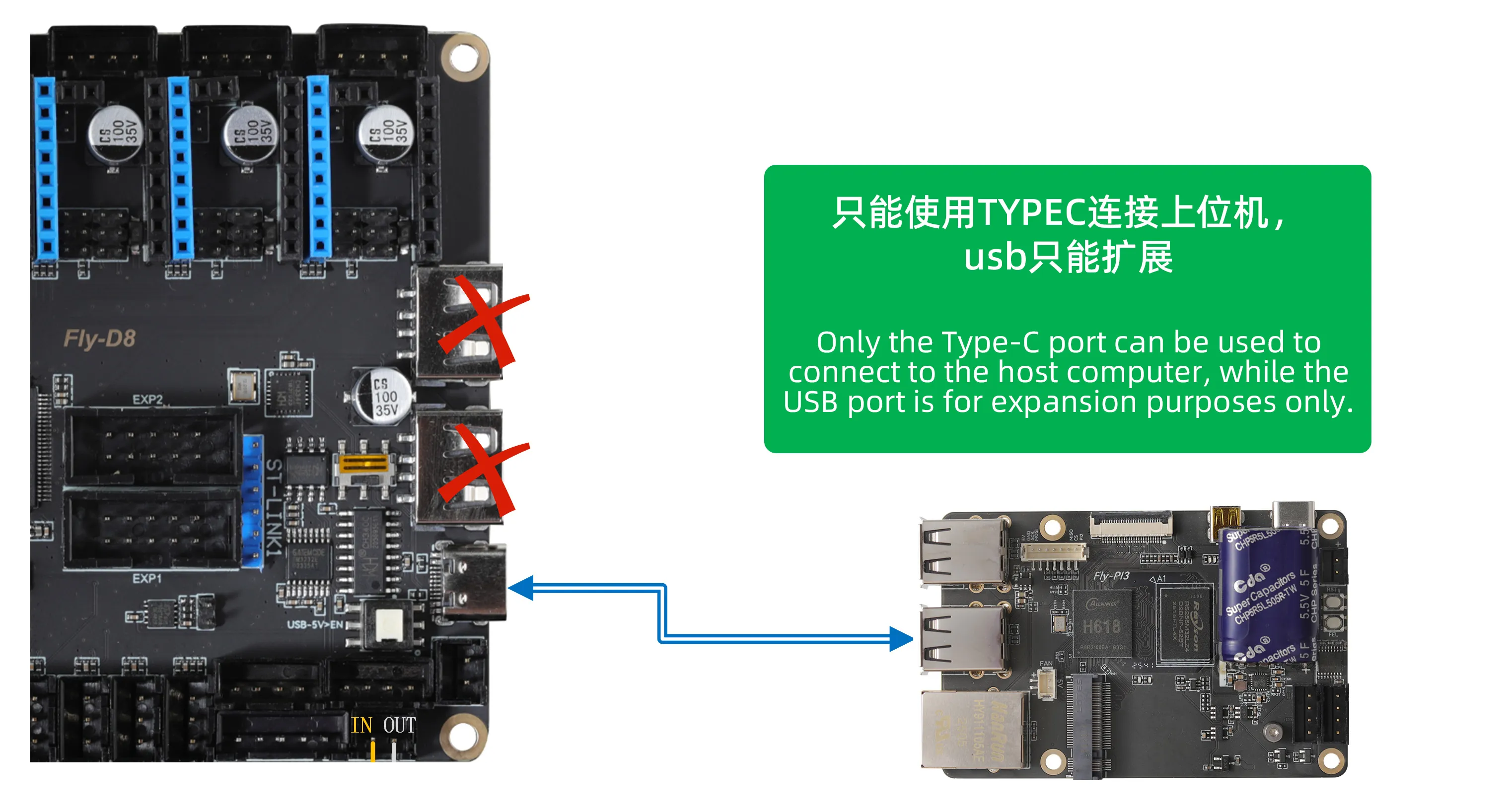
Connection Requirements:
- Use a high-quality Type-C data cable to ensure stable data transmission.
- It is recommended to avoid excessively long cables (not exceeding 1.5 meters).
- Connect to a standard USB-A port on the host computer.
USB Interface Function Description
Integrated Architecture Explanation
The RS232 serial port and USB expansion function on the Fly-D8 mainboard are two completely independent functional modules, only physically integrated on the mainboard.
The Fly-D8 mainboard is equipped with two USB interfaces, each with different functions:
1. Type-C USB (Host Interface)
- Function: Dedicated for connecting to the host computer.
- Power Switch: There is a
USB-5V>ENswitch next to it, used to control the 5V power output of the Type-C interface.- Pressed Down: Turns ON the 5V output from the Type-C interface (can power the host computer).
- Popped Up: Turns OFF the 5V output from the Type-C interface.
For regular use, it is recommended to keep the USB-5V>EN switch popped up (5V output OFF) to avoid:
- Conflict with the host computer's own 5V power supply.
- Potential power backflow issues.
- Protecting the host computer's USB interface.
Only press the switch (turn 5V output ON) when the host computer needs additional power from the Type-C interface.
2. USB-A (Device Expansion Interface)
- Function: Used for expanding peripherals, supports connecting:
- USB cameras
- USB drives/storage devices
- Other standard USB devices
- Independent Module: The USB expansion function is a completely independent module, only physically integrated on the mainboard.
USB/RS232 Mode Switching
Function Selection Explanation
The Fly-D8 mainboard uses a DIP switch to select between the USB expansion function or the RS232 serial port function on the same physical interface.
DIP Switch Settings
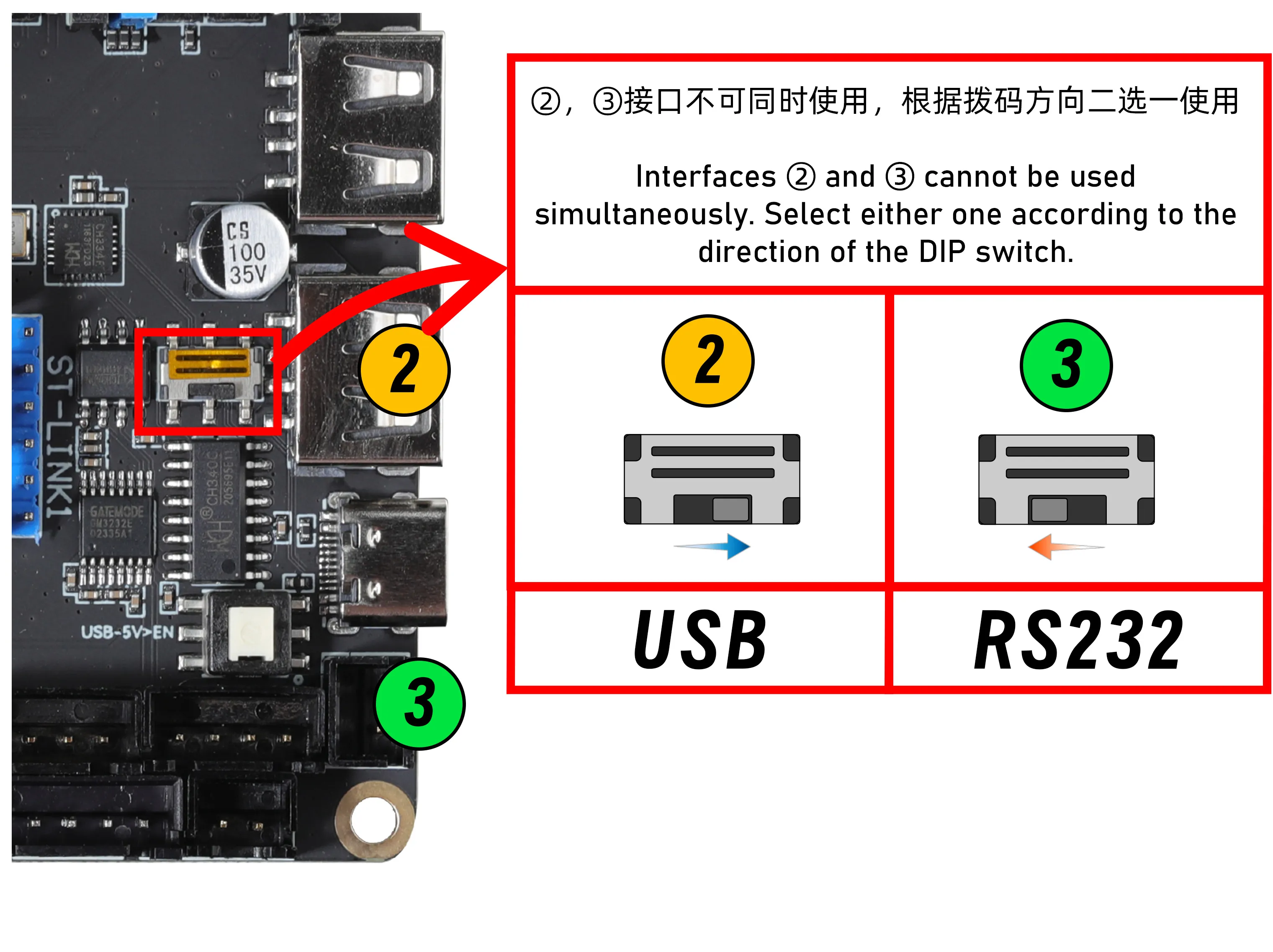
| DIP Direction | Function Mode | Corresponding Interface | Typical Use |
|---|---|---|---|
| Right | USB Expansion Mode | USB-A Interface ❷ | Connect USB devices like cameras, USB drives, etc. |
| Left | RS232 Serial Port Mode | RS232 Interface ❸ | Connect toolboards supporting RS232 communication. |
Mode Switching Precautions
- Mutually Exclusive: USB expansion and RS232 serial port functions cannot be enabled simultaneously; only one can be selected.
- Firmware Compatibility: When using RS232 function, the toolboard must support RS232 communication and have the RS232 firmware flashed.
- Independent Modules: The RS232 serial port and USB expansion are two independent functional modules, only physically integrated on the mainboard.
Common Issues and Troubleshooting
Issue 1: Host Computer Cannot Recognize D8 Mainboard
Troubleshooting Steps:
- Confirm connection is made via the Type-C interface.
- Check the status of the
USB-5V>ENswitch next to the Type-C interface (for regular use, it is recommended to be popped up/5V output OFF). - Check the quality of the data cable; try replacing it.
- Verify that the host computer's USB port is functioning normally.
- Check if the mainboard is receiving normal power supply.
Issue 2: USB Device Not Recognized
Troubleshooting Steps:
- Confirm the DIP switch is set correctly (Right for USB Expansion Mode).
- Check USB device compatibility.
- Verify the USB device works normally on another host.
- Ensure the
USB-5V>ENswitch for the Type-C interface is popped up (5V output OFF).
Issue 3: RS232 Communication Abnormal
Troubleshooting Steps:
- Confirm the DIP switch is set correctly (Left for RS232 Serial Port Mode).
- Check the RS232 cable connection, ensure TX/RX are cross-connected.
- Check for common ground (ensure GND connection between mainboard and toolboard).
- Verify the toolboard supports RS232 communication and has the corresponding firmware flashed.
Usage Recommendations
- Type-C Connection: When connecting to the host computer, it is recommended to keep the
USB-5V>ENswitch popped up (5V output OFF) to avoid power conflicts. - Function Selection: Choose between USB expansion or RS232 serial port function based on needs; they are independent modules.
- RS232 Connection: When connecting to an RS232 toolboard, switch the DIP switch to the left.
- USB Expansion: When connecting USB devices like cameras, switch the DIP switch to the right.
- Safe Operation: All mode switching operations must be performed with the power OFF.
- Firmware Compatibility: Before using the RS232 function, confirm the toolboard has the RS232 firmware flashed.