CAN Bridging
CAN bus is a serial communication protocol bus used for real-time applications, which can transmit signals using twisted pair cables and is one of the most widely used field buses in the world. The CAN protocol is used for communication between various components in vehicles to replace expensive and cumbersome wiring harnesses. The robustness of the protocol has extended its application to other automation and industrial applications. Features of the CAN protocol include complete serial data communication, providing real-time support, transmission rates up to 1Mb/s, 11-bit addressing, and error detection capabilities. On 3D printers, CAN bus is used to reduce the number of wires connecting the print head to the mainboard; originally requiring more than ten wires, only four wires are needed after using CAN, greatly reducing the number of wires and decreasing wiring difficulty. This chapter provides only a brief overview of CAN bridging usage.
Important Tips
- The default CAN speed of the FLY system is
1M; it is recommended that the tool board and mainboard also have firmware with a1Mspeed. - The tool board comes with the factory-installed
Katapultfirmware, with a CAN speed of1M. - If the tool board is under the
Katapultfirmware, there will be an LED on the mainboard flashing. This indicates that theKLIPPERfirmware needs to be flashed; otherwise, normal connection cannot be established. - Please use a multimeter to measure the resistance value between
CANHandCANLwhile powered off to ensure it is around60Ω.
Flashing Mainboard Firmware
- Ensure that the firmware burned onto the C5 mainboard is the
USB Bridge CAN Firmware Configuration. - Below is the button for flashing and searching for CAN IDs.
- USB Bridge CAN Firmware Configuration
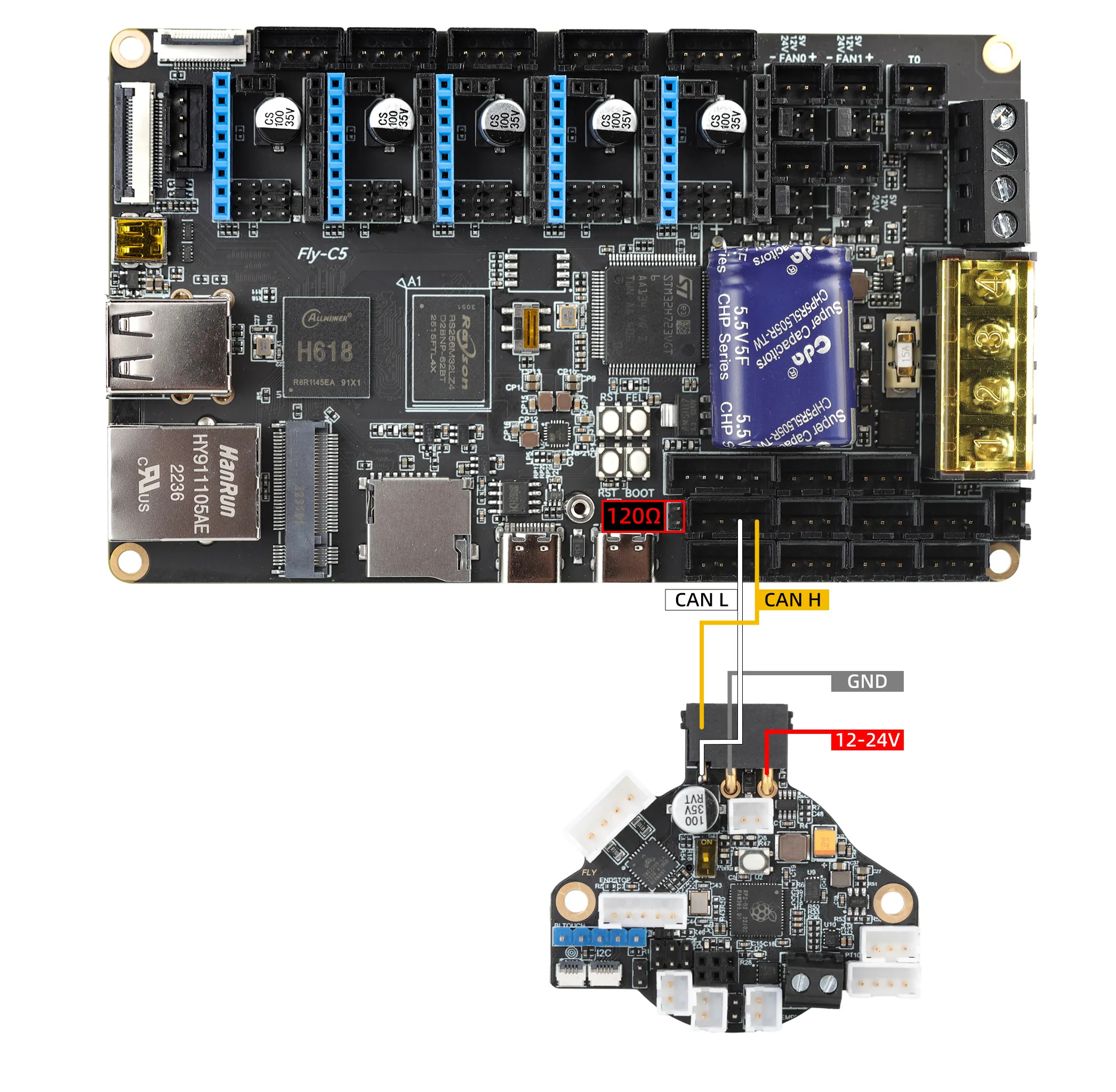
Tool Board Connection to Mainboard Using CAN
- There are many models of tool boards; this section only introduces the wiring tutorial for the C5.
- Note that the power line of the tool board is not connected to the CAN port but to the 12V-24V power line.
- Note that the
120Ωjumper must be connected.