rs232
Diagram of KF Wiring
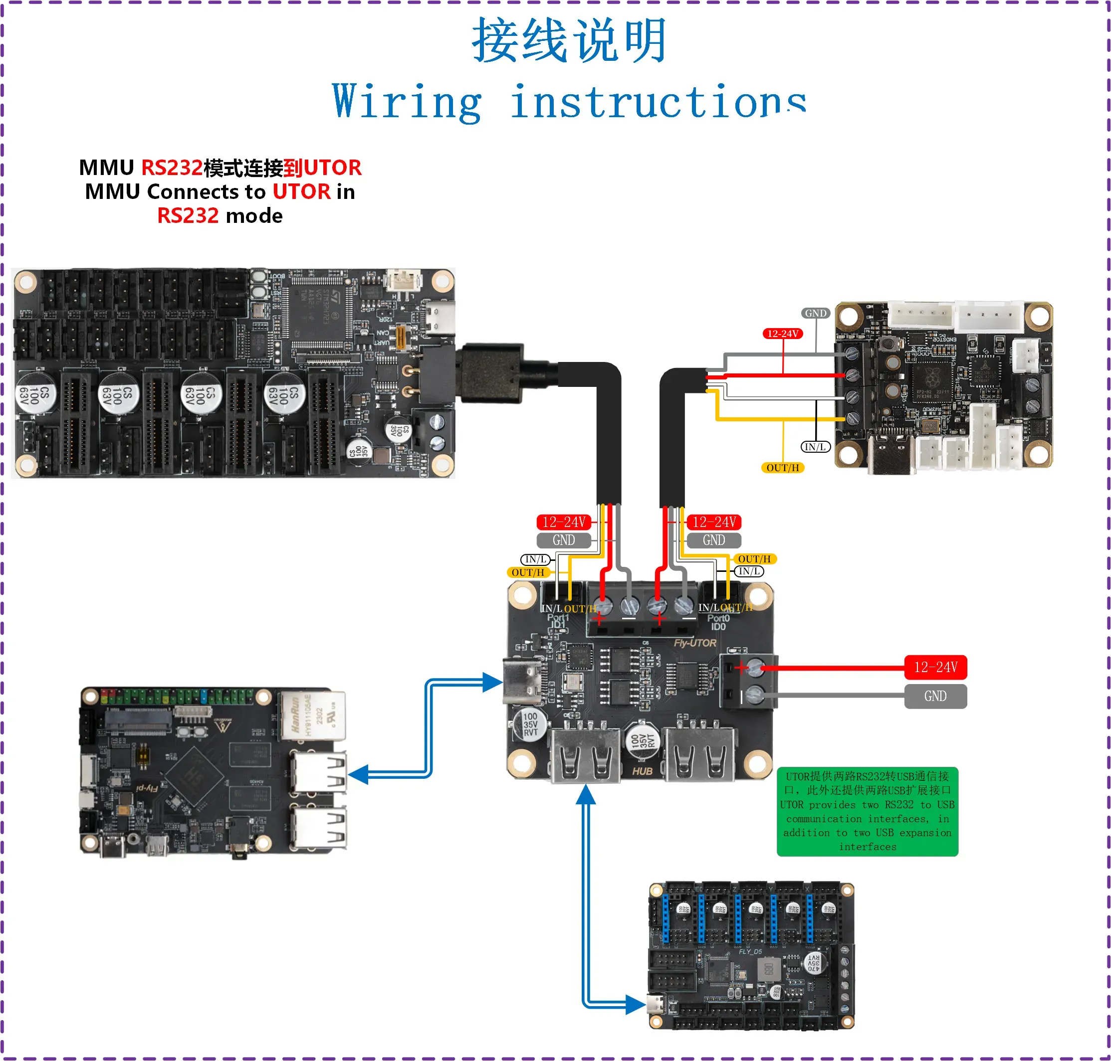
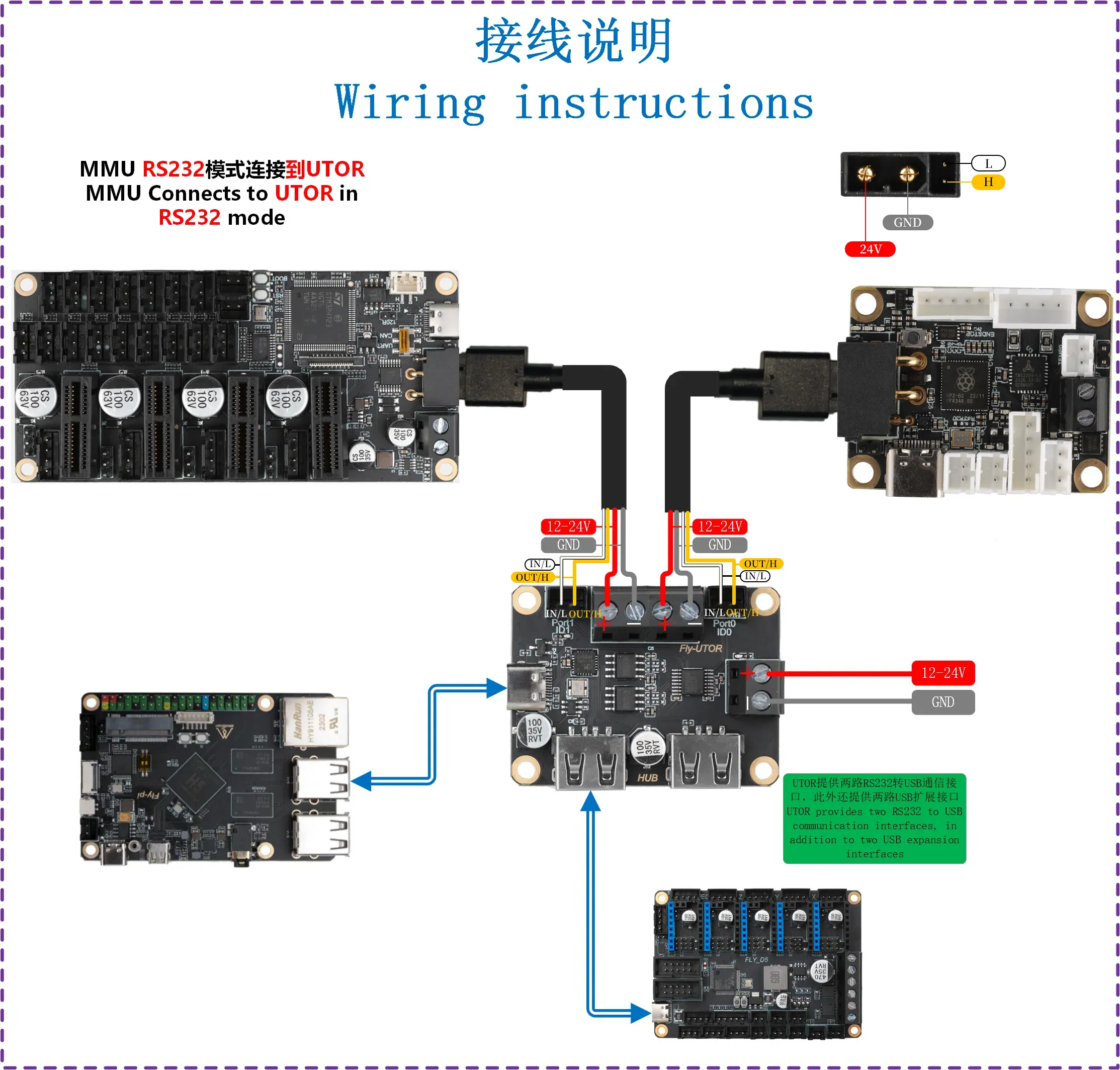
Diagram of XT30 Wiring
RS232 Firmware Compilation
Start Compilation
- A host machine with the installed
klipperservice is required Connect via SSH over the network - Make sure the device is connected to the host machine
- Note: Please use a regular host machine, such as a Raspberry Pi FLY board, etc. If it's a modified host machine (e.g., WiFi stick, Redmi, etc.), due to too many issues, we cannot provide technical support for these machines
- To switch from the
ROOTuser to a regular user, you can enter the command below - Do not use the
ROOTuser - For the fly user, you can directly enter:
su fly. For non-fly users, please replace<your host machine username>with your host machine's username!
su <your host machine username>
- 请确保上位机可以正常联网
- 固件编译前需要使用SSH通过网络登录上位机
- 请不要使用串口工具登录上位机
Klipper固件编译和配置页面操作说明
请确保键盘输入法为半角模式,即英文模式
- 键盘上键
↑,下键↓,用于上下移动光标来选中菜单项 - 确认键
Enter或 空格键Space,用于勾选菜单或进入子菜单 - 退出键
ESC,用于返回上一级菜单 Q键,用于退出Klipper固件配置页面Y键,在退出Klipper固件配置页面时,如果有提示,则点击Y键保存配置文件
如果配置页面选项比较少,请先勾选[ ] Enable extra low-level configuration options,用于显示部分隐藏选项
Below is an introduction on how to compile the firmware:
-
After connecting to SSH, enter the following command and press Enter:
cd ~/klipper && rm -rf ~/klipper/.config && rm -rf ~/klipper/out && make menuconfig -
Among them,
rm -rf ~/klipper/.config && rm -rf ~/klipper/outis to delete previous compilation data and firmware, andmake menuconfigis to compile the firmware. After execution, the following interface should appear: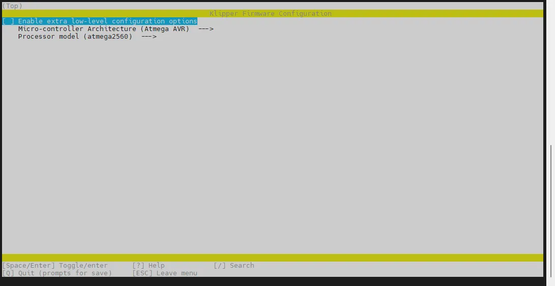
-
Select Enable extra low-level configuration options and press Enter
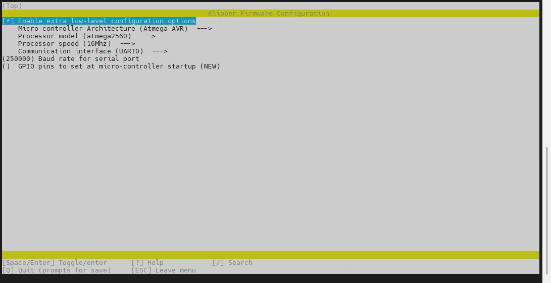
-
Enter the menu Micro-controller Architecture and then select Raspberry Pi RP2040/RP235x and press Enter

-
Select Bootloader offset, choose: NO bootloader
-
Select Communication interface, choose: UART0 on GPIO0/GPIO1

- Select GPIO pins to set at micro-controller startup, input: !gpio18
Please enter !gpio18 in English input mode.

- Press the
Qkey, a Save configuration prompt will appear, then press theYkey
- Now the configuration should be saved and you should exit to the command line interface
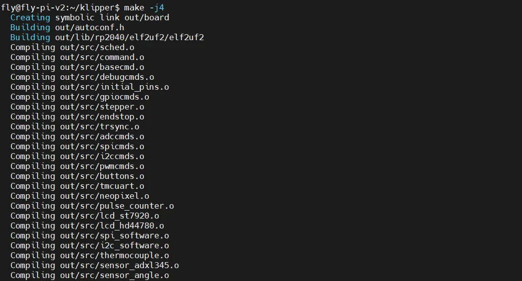
- Enter the following command to start compiling, it may take some time
make -j4
-
If the output below appears, the compilation is successful
Linking out/klipper.elf
Creating uf2 file out/klipper.uf2
Enter Bootloader Mode
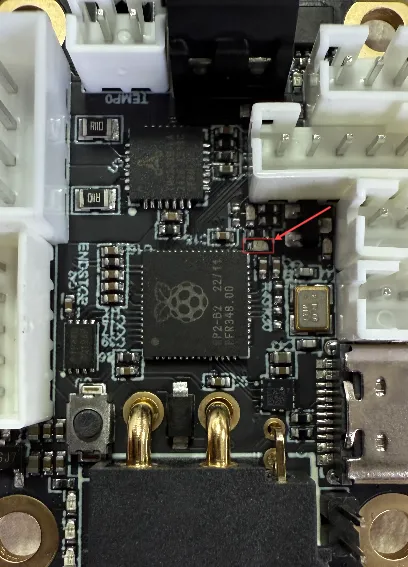
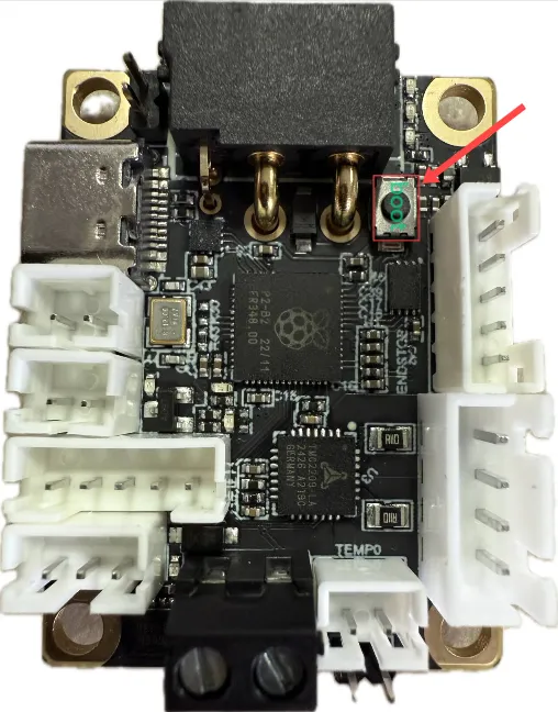
The arrow points to the BOOT button
- With the tool board completely powered off, press and hold the BOOT button, use a Type-C data cable with data transfer capability to connect the tool board to the host computer's USB port, release the BOOT button after correctly connecting to the host computer.
Confirm Entering Bootloader Mode
- Ensure the host computer can connect to the network normally and ensure that the data cable connecting the lower-level machine to the host computer has data transfer capabilities.
- After SSH connecting to the host computer, input
lsusband press Enter. If the information circled in the image below appears, you can proceed to the next step.- If there is no feedback at all, this is a problem with the host computer system, and we are unable to help. You need to replace a confirmed normal system or replace the host computer.
- If the
lsusbcommand is not found, you can execute this command to install it:sudo apt-get install usbutils
- The suffix
OpenMoko, Inc. rp2040has the basis for judgmentXX, whereXXis variable.- Some host computers may display incompletely or not display due to system problems.
Burn RS232 Firmware
- Please note that the current toolboard is in firmware burning mode and can only burn firmware with a .uf2 suffix.
- Use the following command to burn the firmware to the toolboard.
cd && cd ~/klipper/
make flash FLASH_DEVICE=2e8a:0003
If this is the first burn after writing the system with the host machine, you may see a prompt similar to the one circled in red below — partial red prompts are normal and not an error.

Confirm Firmware Startup
- If the firmware starts up normally, the LED will light up as shown in the image below.
