RS232 Toolboard Wiring and Configuration Guide
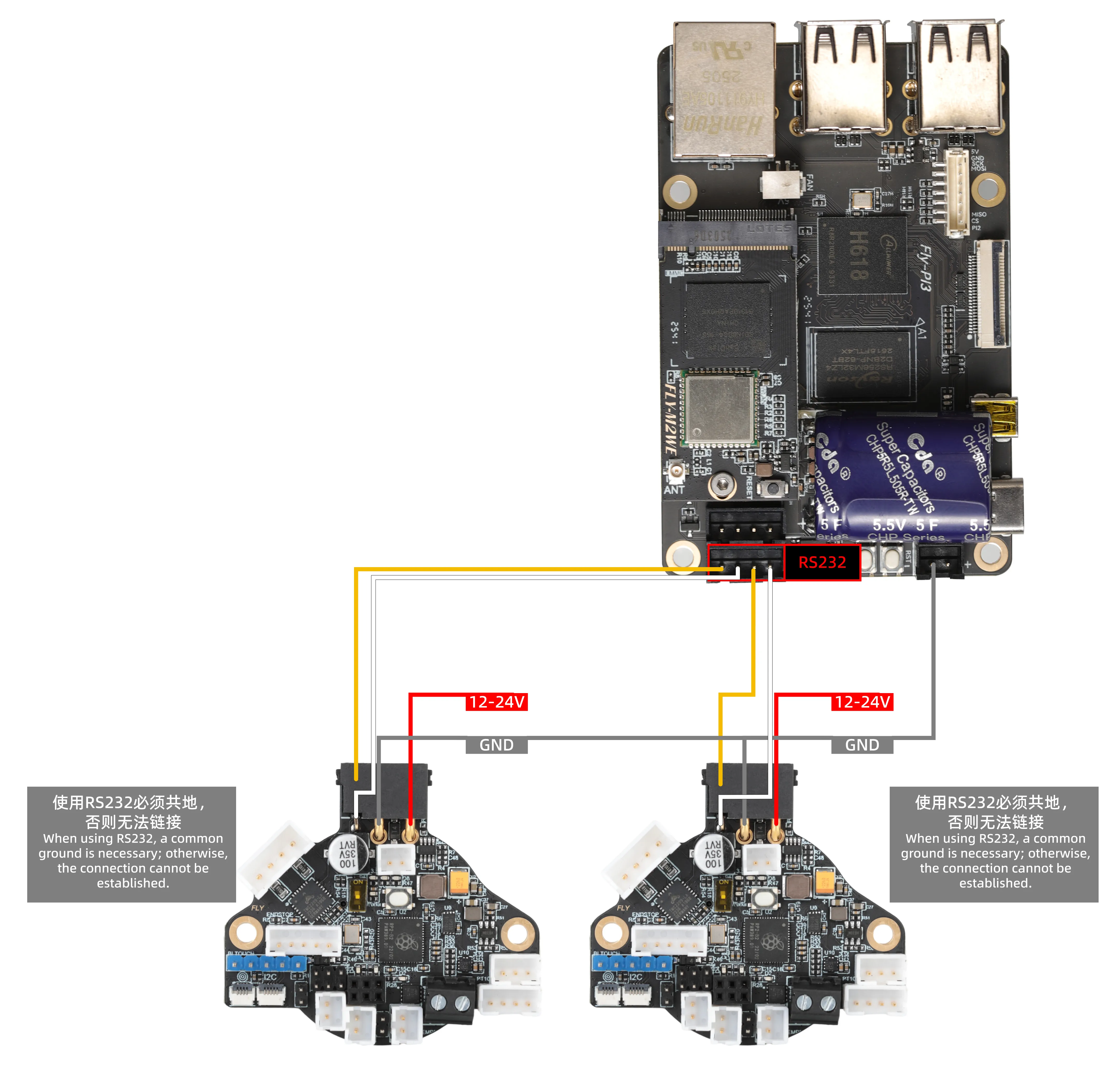
- RS232 Reference Wiring
Interface Configuration Guide
Notes
Important Preparation
- Firmware Requirements:
The toolboard must be flashed with RS232 firmware, otherwise communication will not be possible. - Must Share Ground:
⚠️ Before connecting the toolboard, ensure it shares the same power source asC8Por connect the toolboard's GND to the mainboard's GND (sharing the same24V/12Vpower supply will suffice). - Interface Features:
- Dual RS232 interfaces support independent use of both simultaneously
- Klipper's
serial:parameter is hardware-fixed and cannot be modified
Wiring Standards
|
|
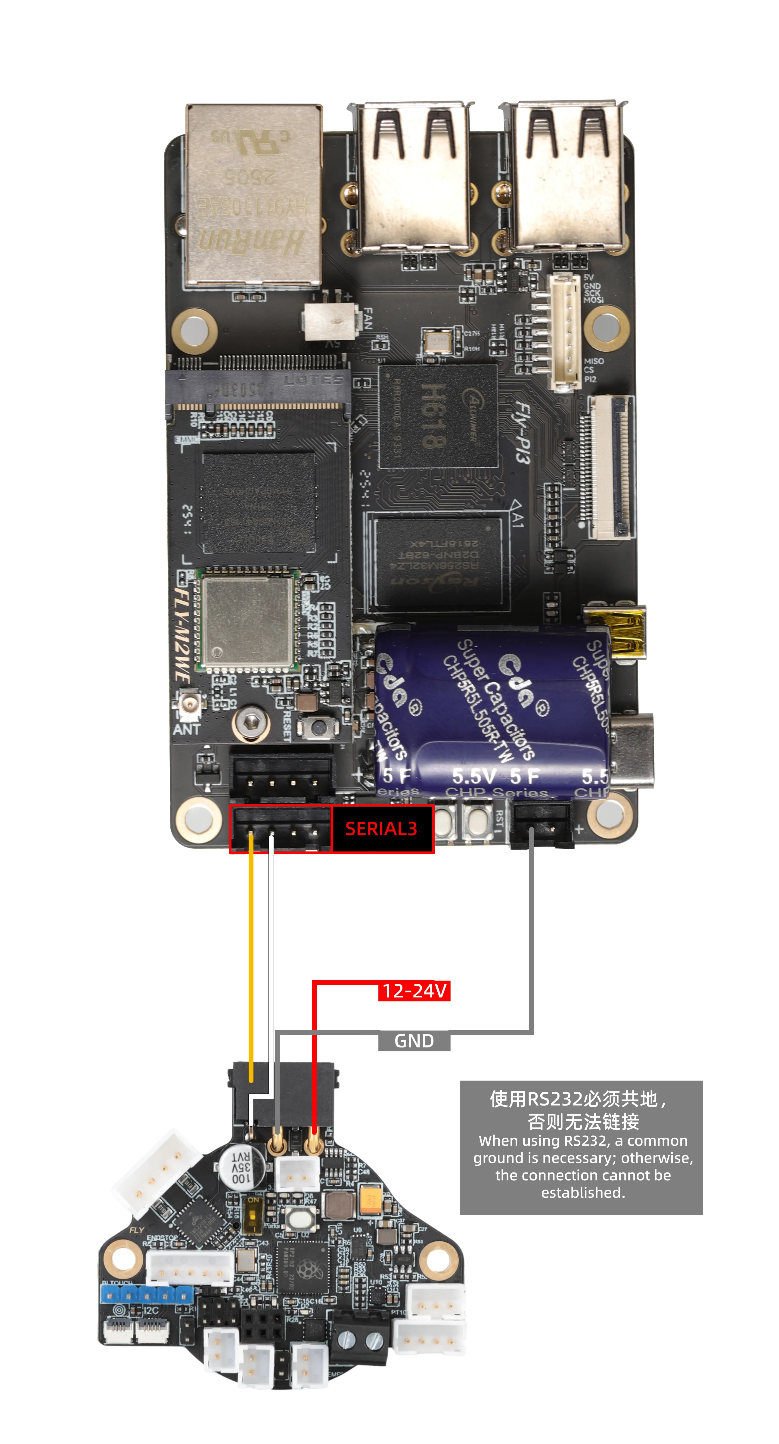
- Left Interface (SERIAL3)
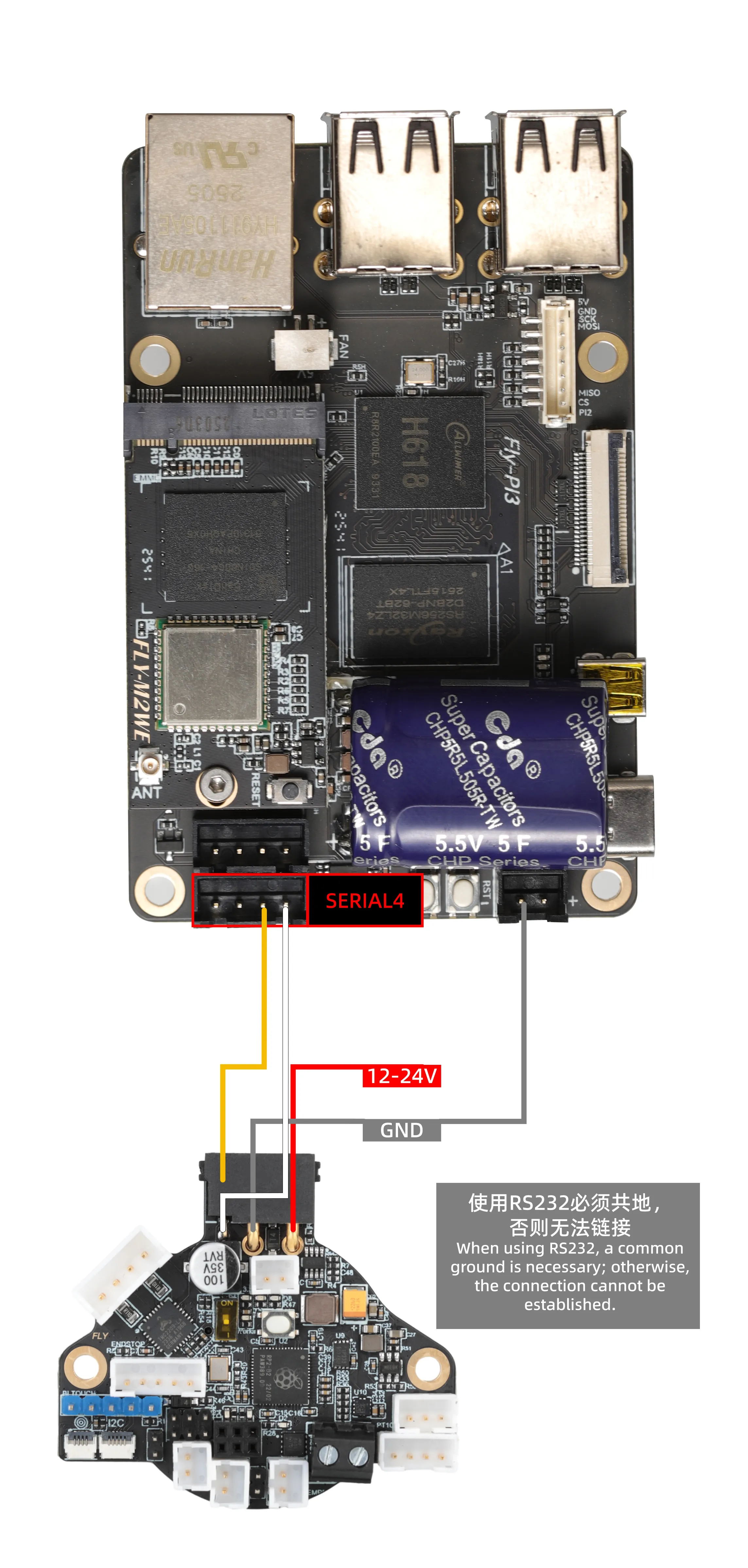
- Right Interface (UART4)
Configuration Steps
- Edit printer.cfg
[mcu Laser]
serial: /dev/serial3  # Fixed device node for the left interface
baud: 250000
restart_method: command - Key Configuration Notes
Laserin[mcu Laser]can be customized/dev/serial3is the dedicated node for the left interface and cannot be changed
Configuration Steps
- Edit printer.cfg
[mcu ToolBoard]
serial: /dev/serial4  # Fixed device node for the right interface
baud: 250000
restart_method: command - Key Configuration Notes
ToolBoardin[mcu ToolBoard]can be customized/dev/serial4is the dedicated node for the right interface and cannot be changed
Configuration ID
- Open your browser and enter the IP address of the host computer in the address bar. For example, if the IP address of my host computer is
192.168.101.179, directly enter it and press Enter.
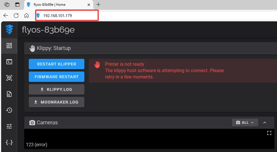
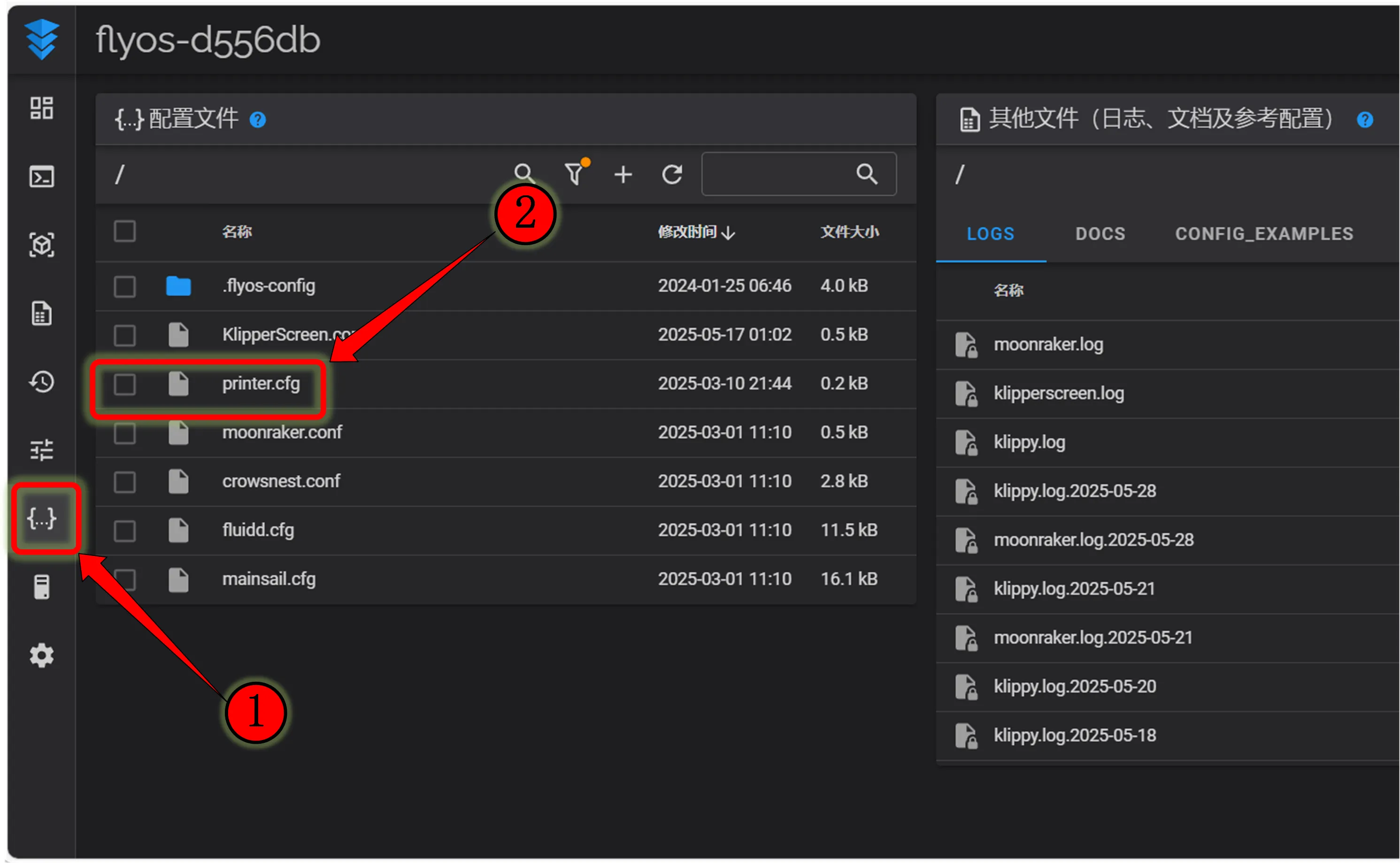
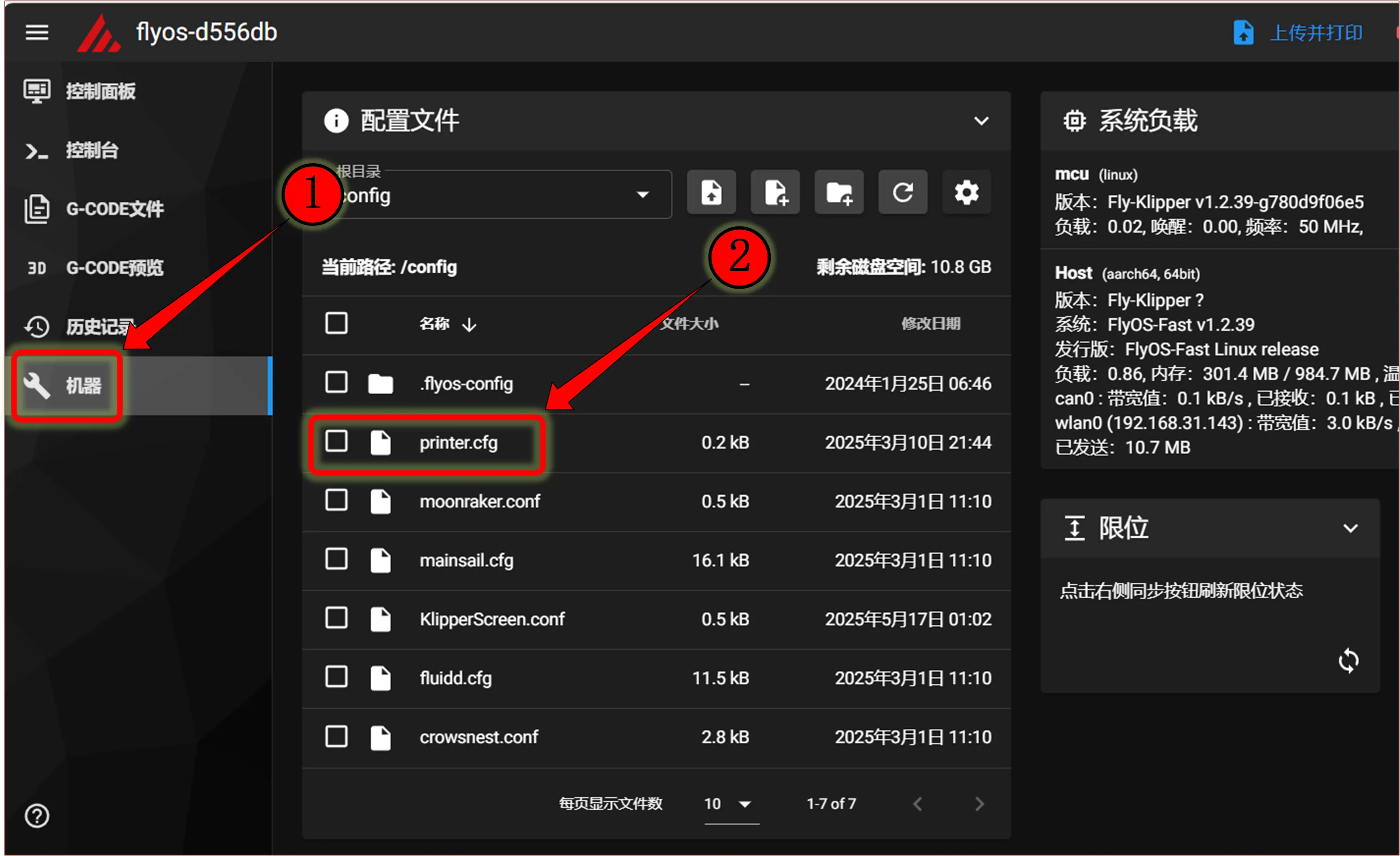
- Open the host computer's web interface and navigate to the configuration section in the left sidebar:
 |
 |
- Fill in the corresponding ID
 |  |
-
Apply Configuration
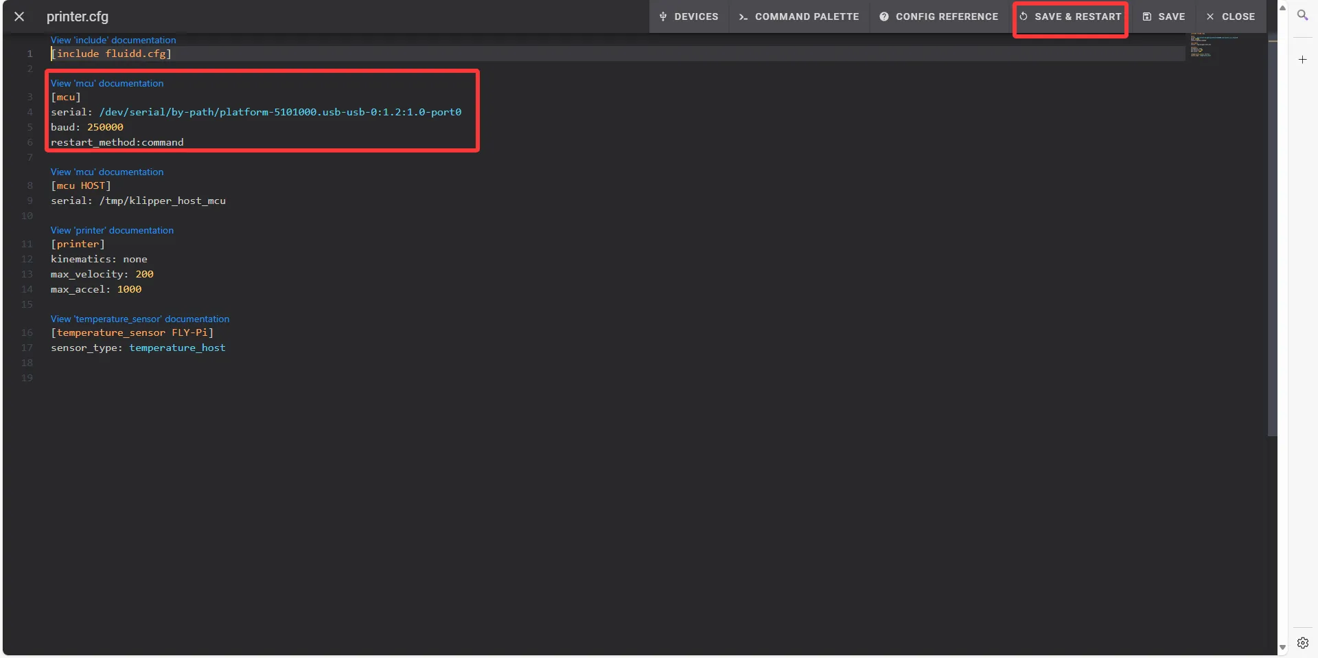
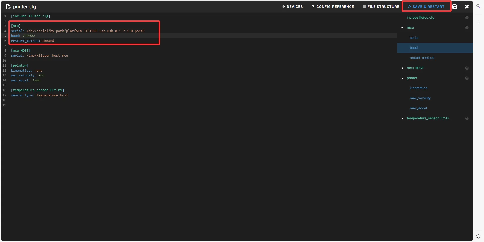
- After pasting the configuration code into the appropriate area
- Click SAVE & RESTART in the top-right corner
-
If Klipper displays
ADC out of range, this is normal. Connect the heated bed and thermistor to the mainboard, configure the thermistor pins for the nozzle and heated bed, then save and restart.
Loading...