Motherboard Wiring
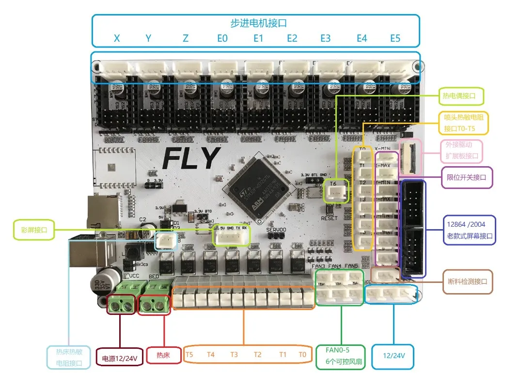
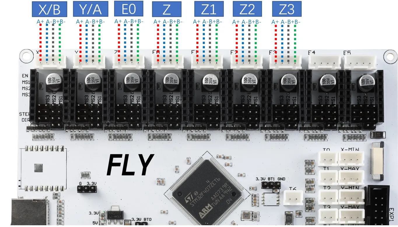
Interface Diagram
Interface Description
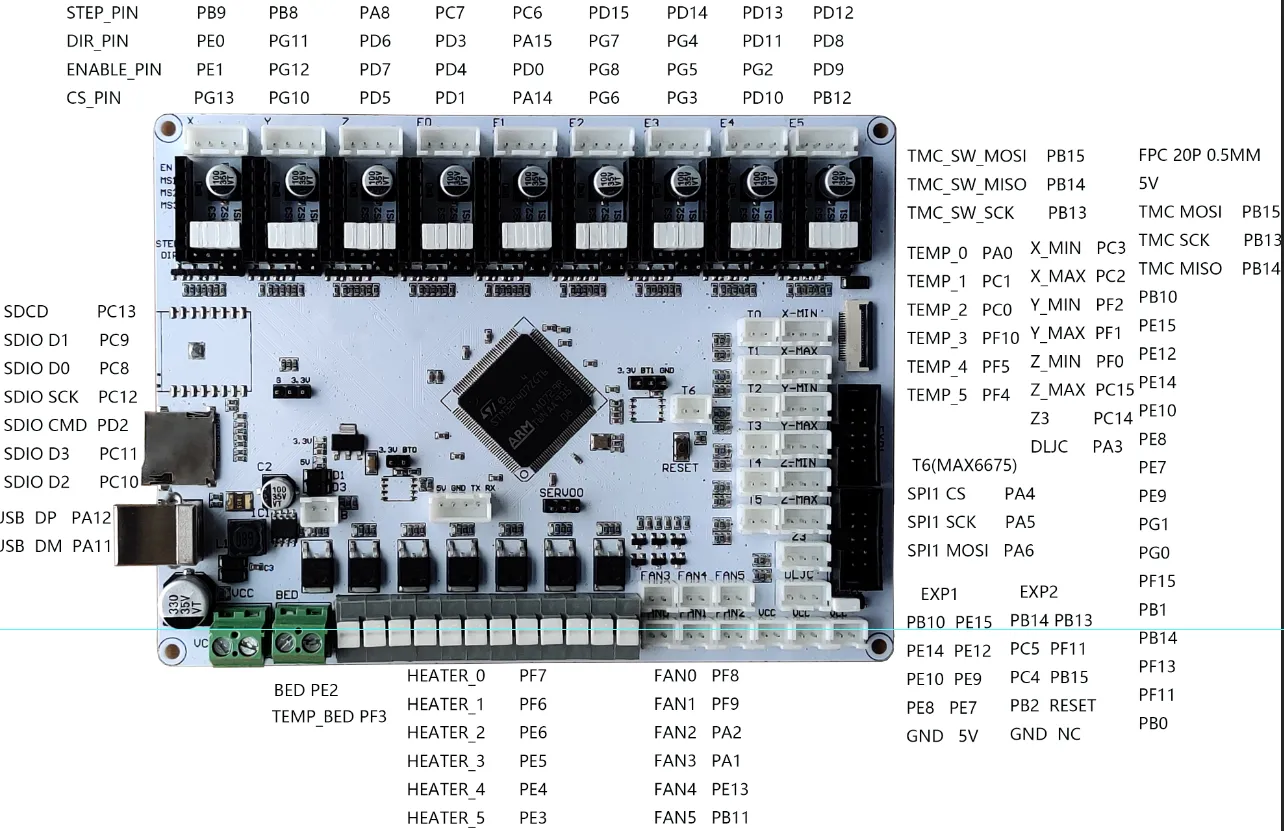
Pin Description
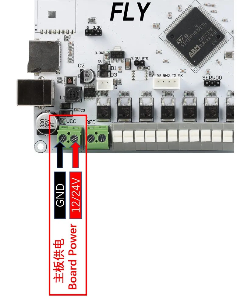
Power Wiring
Driver Installation
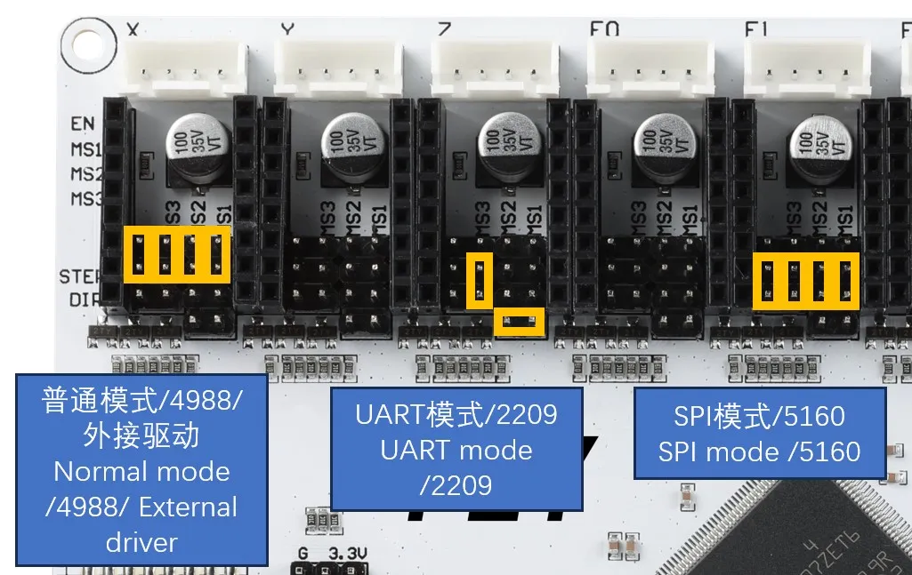
Motherboard Driver Jumper
-
STEP/DIR mode: In this mode, the microstep is set using jumpers and the current is adjusted via a potentiometer. The most common drivers requiring this are A4988, 8825. Please check the microstep configuration table provided by the manufacturer and set accordingly using jumpers.
-
UART mode: Common drivers that use this mode include TMC2208, TMC2209, TMC2226, etc. These driver chips can communicate with the main controller via UART asynchronous serial communication and settings such as microstep, running current, and silent mode can be configured via configuration files.
-
SPI mode: Common drivers that use this mode include TMC5160, TMC2130, TMC2240. These can also configure microstep, running current, and silent mode by modifying the configuration file.
Driver Installation
-
Prior to installation, drivers should be inspected accordingly to avoid damaging the driver or motherboard.
-
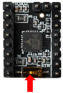
FLY Driver: If the endless zeroing function is not used, please set the DIP switch to position 1; if using endless zeroing function, please set the DIP switch to ON.
 dangerous
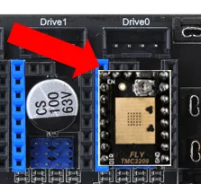
- Warning!!! When installing the driver module, make sure the direction of insertion is correct, with the EN pin at the top-left corner. Otherwise, it may damage the driver or even the motherboard!!! Please apply the heatsink properly to the driver!!!
Stepper Motor Wiring
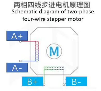
- Regardless of the manufacturer, all two-phase stepper motors have four wires in the end. No matter the color—black, white, green, yellow—it all comes down to four wires. Therefore, these wires need to be grouped into two groups: A and B.
- For a two-phase four-wire stepper motor, we don't need to know which is group A and which is group B. The key is to identify which wires form a group. The motor direction can be adjusted in the configuration.
-
In 3D printers, the most commonly used motors are two-phase four-wire stepper motors, as shown in the diagram below. There are two methods to identify the wiring sequence of a stepper motor:
- Connect any two phase wires and manually rotate the motor shaft. If significant resistance is felt, the two wires are in the same group. Otherwise, they are not in the same group and another pair should be tested.
- Use a multimeter set to continuity mode to test any two phase wires of the stepper motor. If continuity is detected, they are in the same group. If not, try another pair.
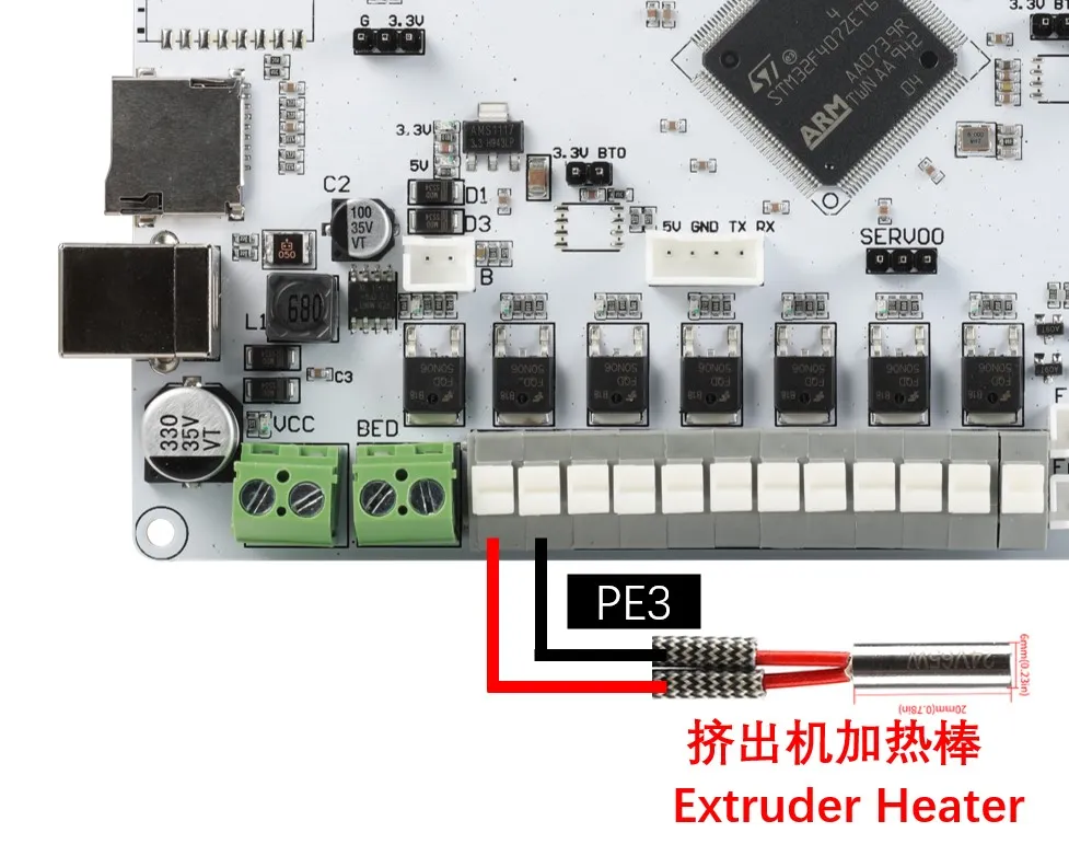
Heater Cartridge Wiring
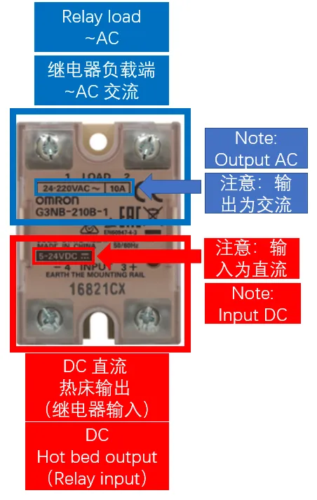
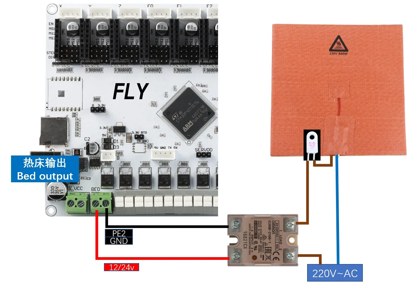
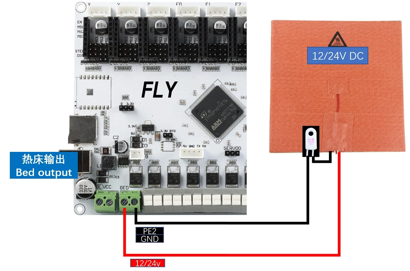
Heated Bed Wiring
-
AC Heated Bed: When wiring a solid-state relay, ensure that the input and output are connected correctly.
-
DC Heated Bed: When using a DC heated bed with onboard MOS, pay attention to the power consumption. The maximum current for a DC heated bed should not exceed 10A. If it does, it is recommended to use an external MOS module to avoid irreversible damage to the motherboard.
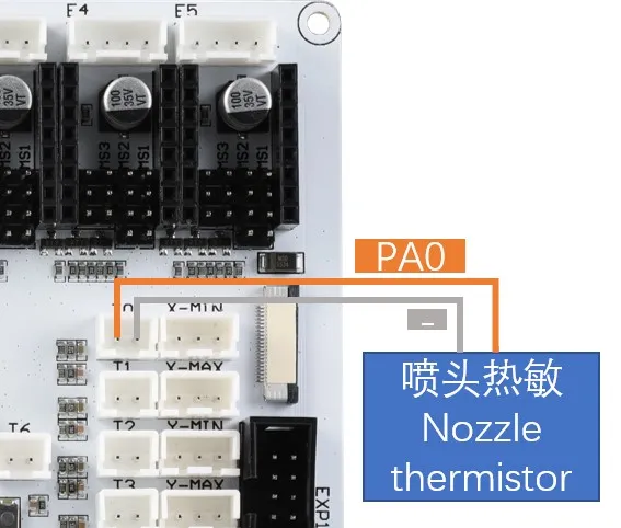
Temperature Sensor Wiring
Thermistor Type Introduction
-
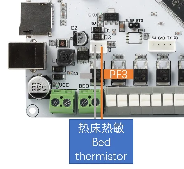
The wiring method for the thermistor is shown in the diagram below. Please consult the seller for the type of thermistor.
-
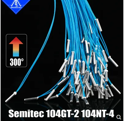
If you purchased the thermistor from fly (as shown below), please set the sensor_type to: ATC Semitec 104GT-2
-
If you have a standard NTC 100K thermistor (as shown below), please set the sensor_type to: Generic 3950


Motherboard Thermistor Wiring
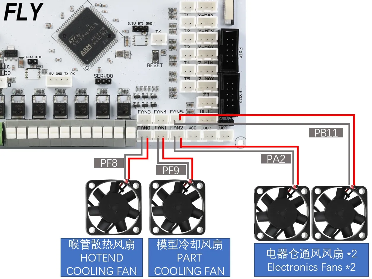
Fan Wiring
-
Fan Wiring
tip- MOS needs to be installed
- Fan wiring
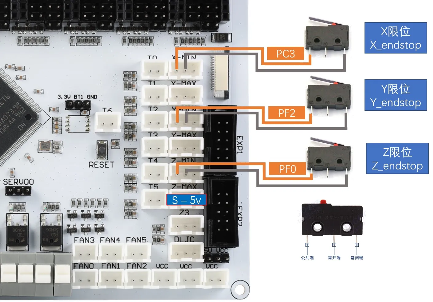
Endstop Switch Wiring
-
Endstop switches come in two types: normally open (NO) and normally closed (NC). In 3D printers, it is generally recommended to use normally closed (NC) switches so that the system will report an error if there is a problem with the endstop switch wiring, preventing unnecessary collisions and printer damage.
Leveling Sensor Wiring
BL-Touch Wiring
-
The BL-touch has five wires in total. Three wires form the first group responsible for power supply to the sensor and deployment/retraction of the probe. The second group consists of the ground and signal wires that output the endstop signal. Please carefully verify the wire sequence when connecting the BL-touch, as incorrect wiring may permanently damage the sensor and motherboard!!! The wiring method is shown in the diagram below.

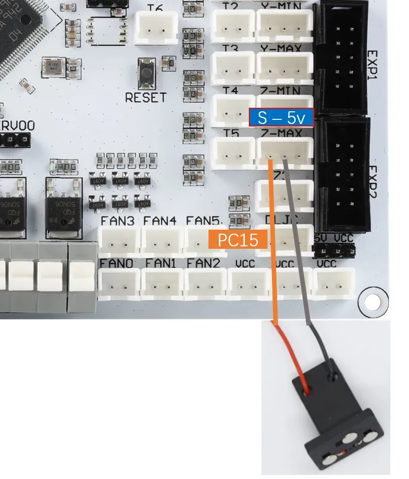
Klicky Wiring
-
Klicky is a third-party leveling sensor that can be made at home with very low cost, offers stable performance, and is highly cost-effective. It is recommended. The wiring method is shown in the diagram below.
-
Project Link: jlas1/Klicky-Probe
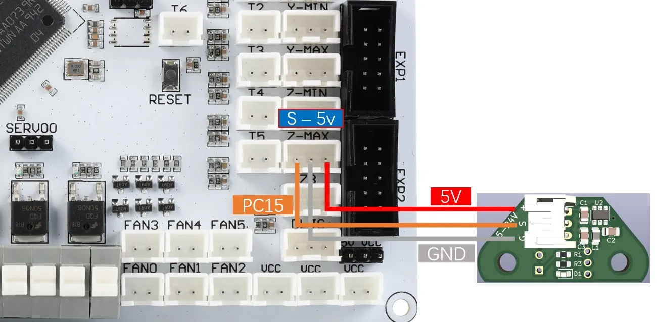
Voron Tap Wiring
-
Tap is a Z probe based on the nozzle, suitable for V2 and Trident printer designs. The entire toolhead moves to trigger an optical switch, offering better accuracy than conventional endstops and can be used with almost all types of print surfaces.
warningIt is not recommended to connect Voron Tap to 24V, as some versions may cause the Tap sensor to burn out. This is not a problem with Fly products but a design flaw in Voron Tap, please be informed!!!
dangerousNote: 5V and GND must not be reversed, otherwise the Tap sensor or even the motherboard may be damaged!!!
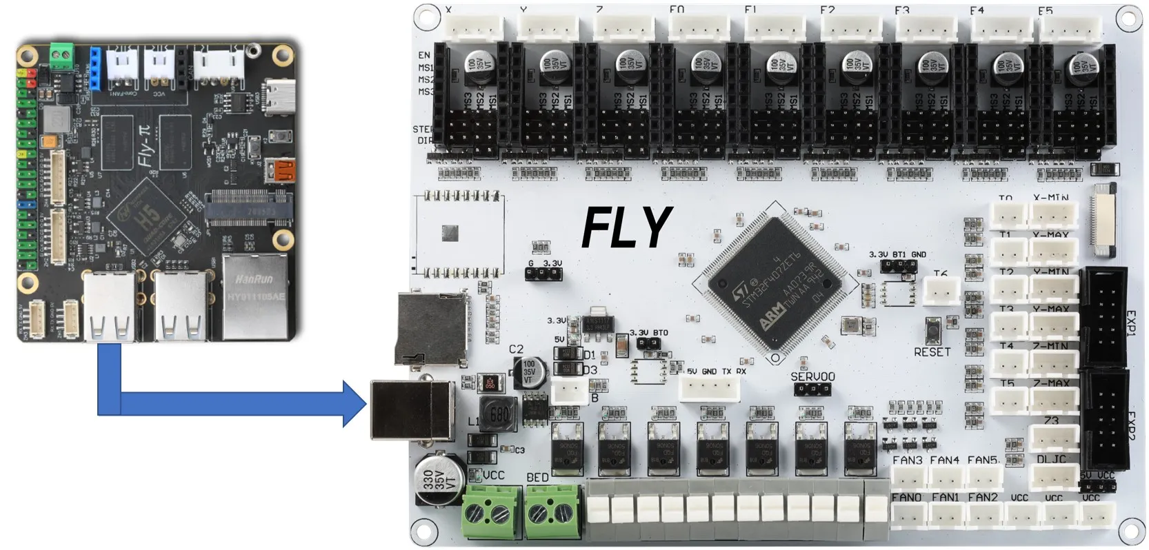
Connecting to the Host Computer
-
The motherboard connects to the host computer via a Type-B USB port, or through a serial port. The former method is described here.