CAN Bridge
CAN bus is a serial communication protocol bus used for real-time applications, which can transmit signals using twisted-pair wires and is one of the most widely used field buses in the world. The CAN protocol is used for communication between various different components in a car, replacing expensive and cumbersome wiring harnesses. The robustness of this protocol has extended its use to other automation and industrial applications. The features of the CAN protocol include complete serial data communication, real-time support, transmission rates up to 1Mb/s, as well as 11-bit addressing and error detection capabilities. On 3D printers, CAN bus is used to reduce the number of wires connecting the print head to the mainboard. Originally, it required more than ten wires, but with CAN, only four wires are needed, greatly reducing the number of wires and simplifying the wiring process. This chapter provides a brief overview of using the CAN bridge.
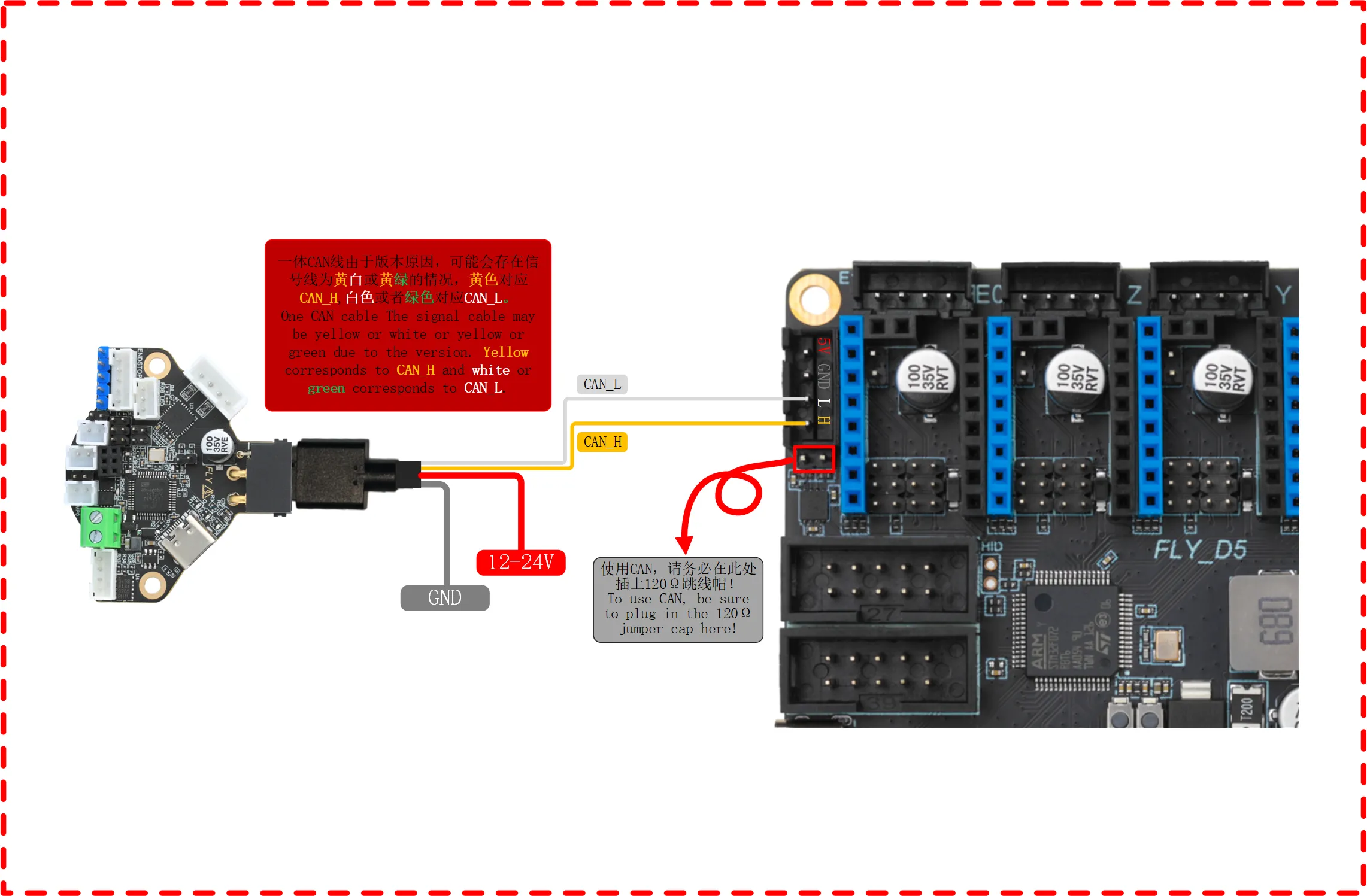
Tool board uses CAN to connect to the mainboard
- Note that the power line of the tool board is not connected to the CAN port, but to the 12V-24V power line
- Note that the 120Ω jumper must be installed
Flashing the mainboard firmware
- Ensure that the firmware burned onto the D5 mainboard is the
USB bridge CAN firmware configuration
Search ID
CAN Configuration and ID Search
- If you need to use CAN, please ensure that your host computer has performed CAN configuration.
Please ensure that the motherboard is properly connected to the host computer before performing the following operations.
Please ensure that the CAN network of the host computer, the CAN rate of the bridged motherboard, and the rate of the CAN tool board are all identical.
Precautions Before Searching for Devices
- Before searching for the CAN ID, please first connect to SSH
- Please note that you must log in to SSH via the network, not via serial port
- Please ensure that a UTOC is connected or a motherboard with the CAN bridge firmware flashed is used, and ensure that the data cable connecting the host computer has data transfer capability
Device Search
- Now that you have successfully logged into the host computer, you can enter
lsusbto search for devices; one of the following situations may occur:- If entering
lsusbprompts that thelscommand is not found, you can install the command using the following instruction:sudo apt-get install usbutils - If nothing happens after entering
lsusb, this is a system issue that we cannot resolve; you need to change the system or use a known good system - If information like in the image below appears, note that this is only a reference. You just need to confirm that
1d50:606fappears: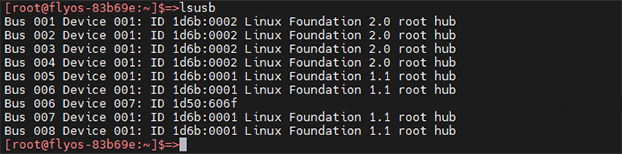
- If entering
1d50:606fis the device you will use this time- If there are multiple
1d50:606f, it is recommended to eliminate one as it may affect subsequent flashing and firmware connection; for example,FLY MINI PADsuggests using the onboard UTOC rather than other CAN bridge devices - If not present, please check that the data cable is properly connected and that the firmware is correctly flashed.
The 1d50:606f must be present before searching for the CAN ID.
Search for CAN ID
- Enter the following command to search for the ID:
~/klippy-env/bin/python ~/klipper/scripts/canbus_query.py can0
- For
FASTsystems, use the following command:
python ~/klipper/scripts/canbus_query.py can0
- If an ID appears and the
Application:at the end showsKlipper, then this ID can be used directly - If an ID appears and the
Application:at the end showsCANBOOTorKatapult, then firmware flashing is required before use
CAN Issue Collection
- Before using
CANfor the first time, it is recommended to read the CAN issue collection document below. - If you cannot find the CAN ID, please refer to the document below
- CAN Issue Collection
Fill in the CAN ID into the Configuration
 |
 |
-
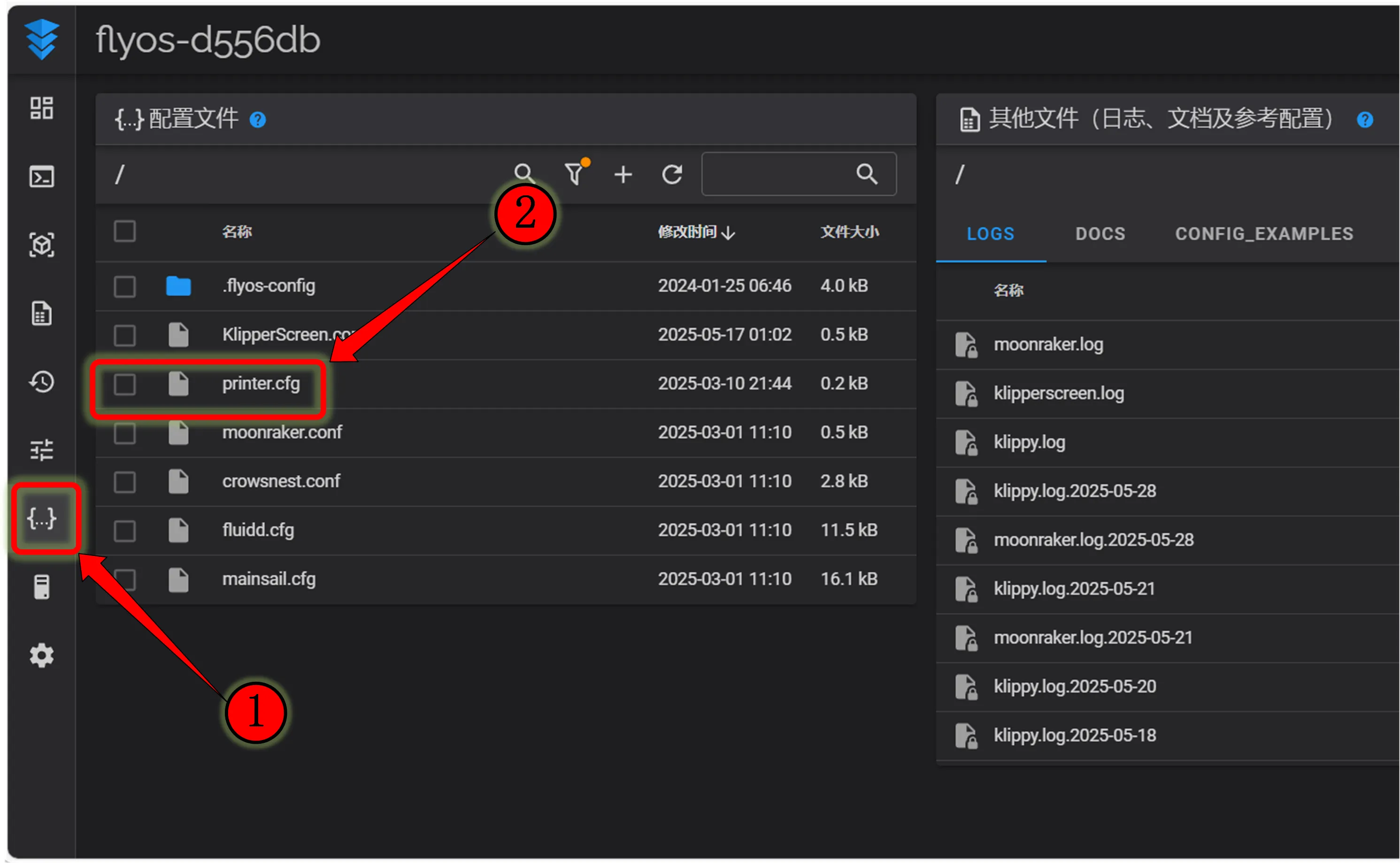
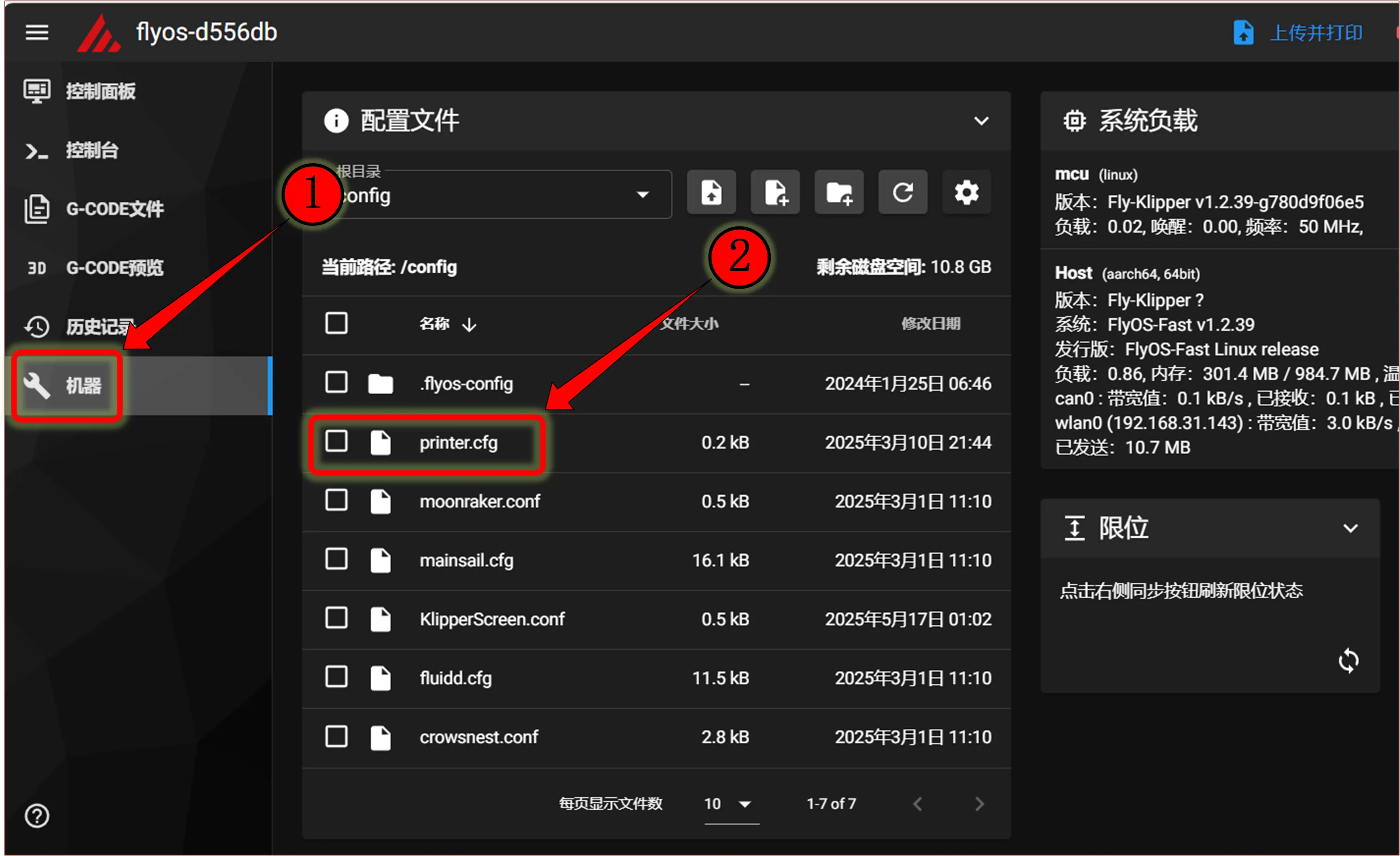
Copy the queried UUID and fill it into the
canbus_uuid:of the[mcu]section in theprinter.cfgconfiguration. After saving and restarting, the motherboard can be connected. If Klipper prompts that the firmware needs updating, ADC errors, etc., it indicates that Klipper has successfully connected to the motherboard. -
If
Application:shows Canboot, it cannot be configured into the configuration; you need to flash the Klipper firmware to proceed.dangerousNote: All IDs appearing in the document are examples. Each motherboard has a different ID; please modify and fill in according to the ID actually obtained.
-
Below is a reference configuration
dangerous[mcu]
canbus_uuid: <Replace with the ID you just queried>- Below is a reference configuration method for the MCU ID in the case of one motherboard plus one tool board
- If it is the motherboard ID, it must be
[mcu]followed bycanbus_uuid:and then the ID you searched for - If it is the tool board, it must be
[mcu tool board name]followed bycanbus_uuid:and then the ID you searched for
