Install BDsensor-m
Connect the sensor cable to the motherboard's EXP1 interface
- If the sensor's cable is not long enough, you can use the delay line in the packaging.
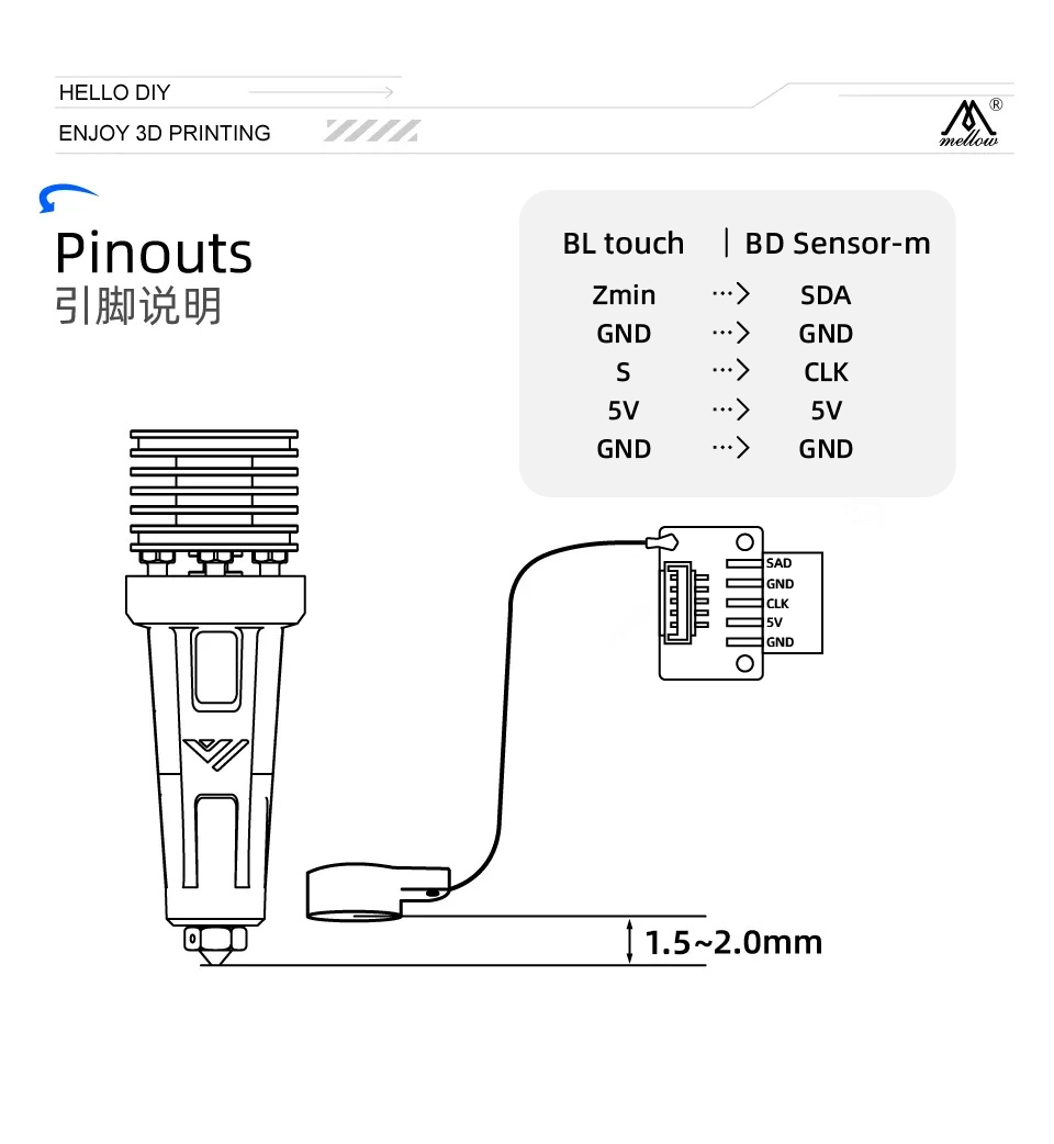
- The CKL and SDA wires of the BDsensor-m can be connected to any GPIO pin on the circuit board. You can also connect the BD sensor cable directly to the Bltouch port, for example:
BLtouch    |    BDsensor-m
5V       -->     5V
GND      -->     GND
S        -->     CLK/SCL    (Input)
GND      -->     GND
Zmin     -->     SDA    (Input/Output)
- Since some pins in the motherboard connector may not be directly connected to the MCU's GPIOs (for example, they may have filtering capacitors or be isolated by MOSFETs, diodes, or optocouplers, but they can also be used if they are isolated by resistors or resistor pull-ups/pull-downs), they cannot be used with
BDsensor-m. And the firmware will report a connection error. For example - The connectors for fans and heaters are isolated by MOSFETs,
- The connectors for temperature thermistors and endstops/probes in some circuit boards are usually connected to GND through filtering capacitors,
-
As shown in the figure below, install the BD sensor near the hot end. STL of mount, STL_mount_VzBot_Goliath short
Install the patch to the klipper firmware
-
Do not do anything not mentioned in the tutorial
-
Discard previously modified klipper files and update klipper
cd
cd ~/klipper
git checkout .
git pull -
Execute the following git command in the user directory to clone the latest code of BD sensor
cd && git clone https://github.com/markniu/Bed_Distance_sensor.git -
Then execute the following command to install
cd  ~/Bed_Distance_sensor/klipper/
./install_BDsensor.sh
Compile firmware here if prompted that the firmware of the upper and lower computers is inconsistent, compile a new klipper firmware
-
Find your own firmware compilation tutorial to compile and flash the firmware
-
Compile firmware
cd ~/klipper/  # go to klipper directory
make menuconfig  # enter klipper compilation interface command
make clean  # clean command
make # compile command -
Burn the firmware to the motherboard connected to the BD sensor
If your printer is running Moonraker, add the following part to moonraker.conf, and then you can update BDsensor by clicking once through the web page or klipperscreen.
[update_manager BDsensor]
type: git_repo
primary_branch: new
channel: dev
path: ~/Bed_Distance_sensor
origin: https://github.com/markniu/Bed_Distance_sensor.git
install_script: ./klipper/install_BDsensor.sh
is_system_service: False
managed_services: klipper
info_tags:
desc=Bed Distance Sensor
Edit printer.cfg
-
Copy this part to your printer.cfg and edit
[BDsensor]sda_pinscl_pin, and don't forget to disable other probe parts, such as BLtouch. You can connect the BD sensor on the motherboard or the CAN module of the tool head. -
Change
speedto 0.8 in[BDsensor]. This is only applicable to z tilt and PROBE_ACCURACY commands. The smaller the value, the higher the accuracy during probing, because the MCU does not read the BD sensor in the main loop in real-time like a normal stopper when homing.[BDsensor] -
To use the BD sensor as a limit switch when the Z-axis homes, change
endstop_pinin[stepper_z]toendstop_pin: probe:z_virtual_endstop -
Make sure there is
[safe_z_home]in printer.cfg -
Change the value in
[bed_mesh]and[z_tilt]or[quad_gantry_level]to 1 (recommended 0.7-1.0mm). The default value in klipper is 5mm, otherwise it is easy to exceed the sensor range. -
Nozzle height is only suitable for setting in
z_adjust:, positive numbers are close to the hot bed, negative numbers are away from the hot bed, other settings for adjusting nozzle height will have bugs -
To enable fast bed scanning, delete the # in front of
no_stop_probe:true -
Here is a configuration example.
[BDsensor]
scl_pin:PC6  # Servo signal port
sda_pin:PC3  # Limit signal port
delay: 20 # 20us per pulse, this value should be >=20 but must be below 50
z_offset:0 # this `z_offset` must be set to 0.
z_adjust:0.0 # z axis adjustment, replace the z_offset function. within -0.3 to 0.3mm
x_offset: -34
y_offset: 0
#no_stop_probe:true # enable this for fast probe, the toolhead will not stop at the probe point.
position_endstop: 0.8 # the Z axis will stop at this position (mm) while homing z, recommend value is 0.4~1.0
#speed:0.8 # this speed only works for the z tilt and PROBE_ACCURACY command.

[stepper_z]
endstop_pin: probe:z_virtual_endstop
#position_endstop: 0.5
homing_speed: 5
second_homing_speed: 0.8

[bed_mesh]
speed: 200
horizontal_move_z:1
algorithm: bicubic

[quad_gantry_level]
horizontal_move_z:1
After installation, check by sending the following gcode commands
M102   S-1     # Read sensor information
M102   S-2     # Read a distance value
Check connection
-
Send
M102 S-1through the console, this is an example of the returned message, if it returns blank or other strings please check the connection and wire orderSend: M102 S-1
Recv: V1.0 pandapi3d.com
Calibration
- Clean the nozzle, then move the Z-axis through the console until the nozzle just touches the bed plate (BDsensor-m will use this position as the zero position, so there is no need for
z_offset, this is why the value in [BDsensor-m] part is 0) - Send the gcode command
M102 S-6through the console, the printer will move the Z-axis slowly upward by 0.1mm each time until it reaches 4mm. Do not run M102 S-6 before installing the sensor, nor turn off the printer power during calibration, otherwise the old calibration data will be deleted. If this happens, just calibrate again - Afterwards, you can check if the BD sensor has been successfully calibrated through
M102 S-5, which will return the original calibration data stored in the BD sensor.
Notes:
-
The best speed for homing the Z-axis is 5
-
If the first original calibration data returned by M102 S-5 is greater than 400, it means the sensor is installed too high and needs to be reinstalled closer to the bed, the recommended value for the first data is 100. Also make sure that the second data value is more than 10 greater than the first data
-
FAQ: What does it mean if the calibration data starts with 1, the second value is 9, and the third value is 24?
-
This means that the resolution between 0-0.1mm is only 9, while the resolution between 0.1-0.2mm is 15. Therefore, it is recommended to recalibrate to make the first resolution 0-0.1mm greater than 10.
-
-
Do not forget to adjust the Z-axis height after running G28 or for these commands
Z_tiltandquad_gantry_level -
The part names must be correctly capitalized and lowercased, otherwise klipper will report
Unknown pin chip name 'probe'